
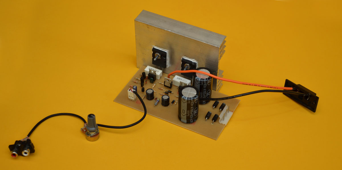
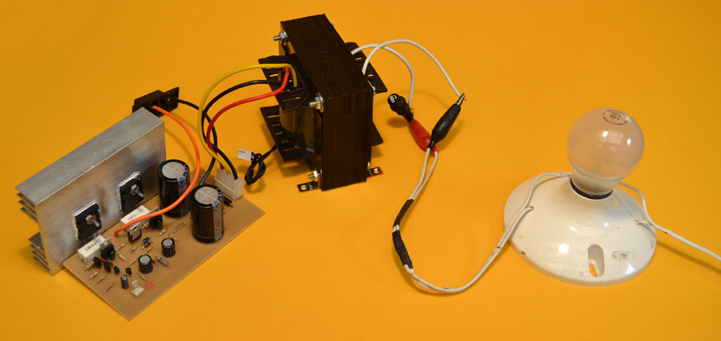
Hi, here we present a 100W Amplifier, a mono version of our acclaimed 200W Stereo Amplifier, we’ve developed a new iteration based on the 400W Mono Amplifier. This upgraded 100W Amplifier boasts enhanced response and fidelity, surpassing its predecessor.
We introduce a 100W sound amplifier featuring an innovative Quasi-complementary configuration, utilizing NPN transistors for both half-cycles. This mono amplifier is based on the popular “Zener” amplifier, well-known in for its exceptional performance.
The “Zener” amplifier earns its name from the zener diode that stabilizes the input differential pair. This design ensures outstanding stability, sufficient power, and minimal harmonic distortion, making it perfect for:
– Amplifying electric guitar preamplifiers
– Boosting bass preamplifiers
– Home audio applications
Its Design is Compact
This amplifier can handle an 8-ohm load. For 4-ohm operation, replace the 2SC5200 output transensors with 2SC3858, MJL21194, or 2SC2922 transistors. Using a 4-ohm load means you can connect two 8-ohm speakers in parallel to the single output. Note that doubling the load from 8 ohms to 4 ohms does not double the power output. With only two output transistors, the power increase is limited to approximately 20%. To achieve higher power outputs, add more transistors in parallel. Each additional pair of 2SC5200 transistors can increase power by around 100W. However, this requires modifying the power supply to provide sufficient power for the added transistors. For a significant power boost, consider adding more transistors in parallel, as seen in the 400W mono version.
Regulation Stage with Zener Diode
One of the standout features of this amplifier is its exceptional stability, which can be attributed to the regulation stage that powers the input differential pair. This stage consists of a zener diode (18-24V) paired with a 4.7K 1W resistor, ensuring a stable voltage supply to the differential pair formed by two A1015 transistors. The zener diode provides a constant and stable voltage, eliminating voltage fluctuations. Unlike other amplifiers that directly tap into the +Vcc voltage, which can lead to voltage variations at the emitter junction of the A1015 transistors, this amplifier maintains a consistent voltage thanks to its regulation stage. This design ensures optimal performance and stability.
We will take a tour of the audio signal
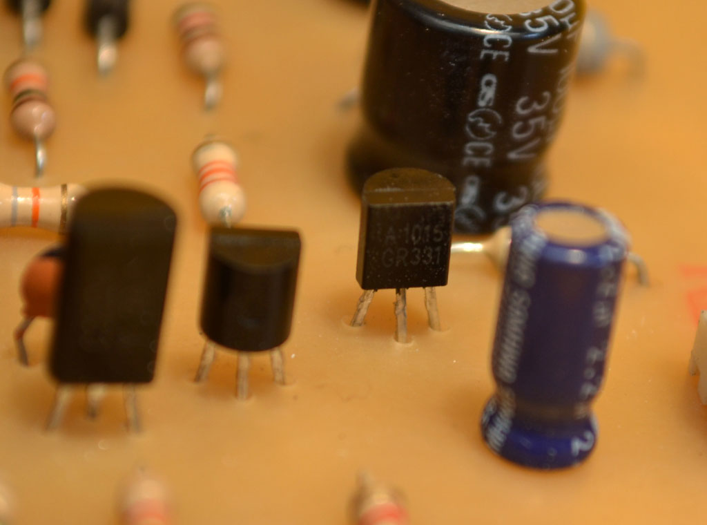
As you review the diagram in the PDF, let’s break down how the amplifier components work: The audio signal enters through a 2.54mm two-pin MOLEX connector and passes through a 2.2 uF capacitor (C1), which acts as a DC decoupling capacitor. This capacitor isolates the sound source or preamplifier from the amplifier, preventing DC voltages from interfering with the signal. The recommended value for this capacitor can range from 0.47 uF to 4.7 uF. Next, the signal reaches a pair of PNP transistors (Q1 and Q2), both A1015 models, configured in a common emitter setup. These transistors receive voltage from the regulation stage and form a “Differential Pair”. The base of Q1 receives the audio signal, while the base of Q2 is grounded at the amplifier’s resting point. A resistor connects Q2 to the speaker output. The collectors of Q1 and Q2 are connected to the negative voltage (-Vcc) through 3.3K resistors. The signal is then passed to the C2229 transistors (Q3 and Q4), which are connected in a collector-to-collector configuration.
Pre-driver Transistors
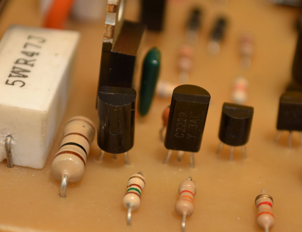
The C2229 transistors (Q3 and Q4) act as pre-drivers, amplifying the signal from the differential pair. These high-performance transistors have been widely used in various applications, including CRT video TVs, high-voltage switching, and audio amplifier drivers. However, it’s essential to note that prolonged use or overloading (e.g., high temperature, current, voltage, or rapid temperature changes) can degrade their performance, even within recommended operating conditions. In this amplifier design, the C2229 transistors operate under relatively quiet conditions and should not overheat. If they do, it may indicate counterfeit transistors or errors in the printed circuit assembly. Important: Authentic 2SC2229 transistors should have a gain (hFE) of 190 or lower. Counterfeit versions can damage the output transistors. If needed, consider replacing them with 2SC1573, 2SC2271, or 2SC1921 transistors.
Driver Transistors
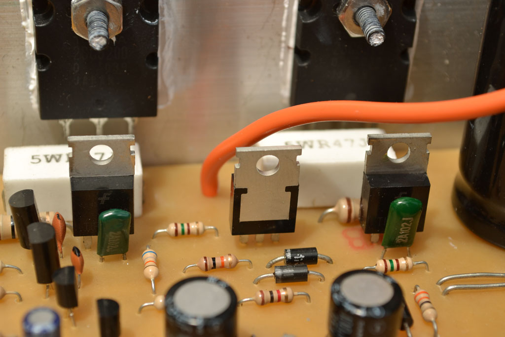
The image shows three medium-power transistors: two TIP42 and one TIP41. These transistors have high current gain, supporting up to 2 amps, making them suitable for switching, audio, and amplifier applications.
In this amplifier design:
– The central TIP42 transistor regulates the BIAS, controlling the current flowing through the output transistors when the amplifier is idle.
– The TIP41 drives the 2SC5200 transistor for the positive half-cycle.
– The right-side TIP42 drives the 2SC5200 transistor for the negative half-cycle. When purchasing TIP transistors, ensure authenticity by measuring the beta (hFE) with a multimeter. The reading should be between 120 and 160. Values outside this range may indicate counterfeit transistors.
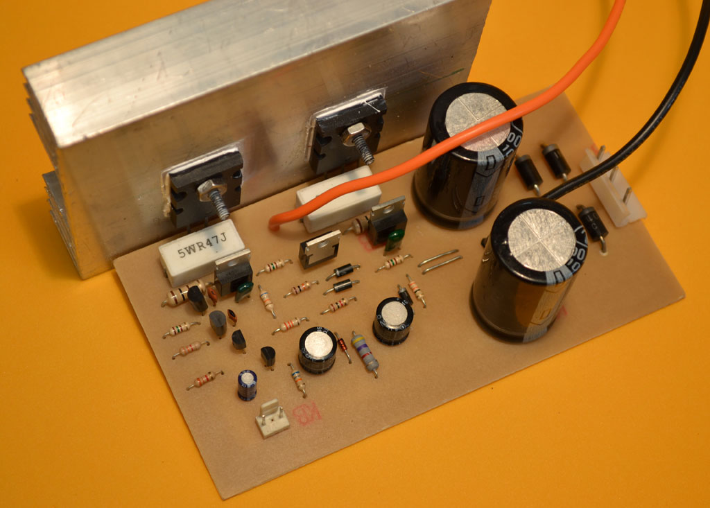
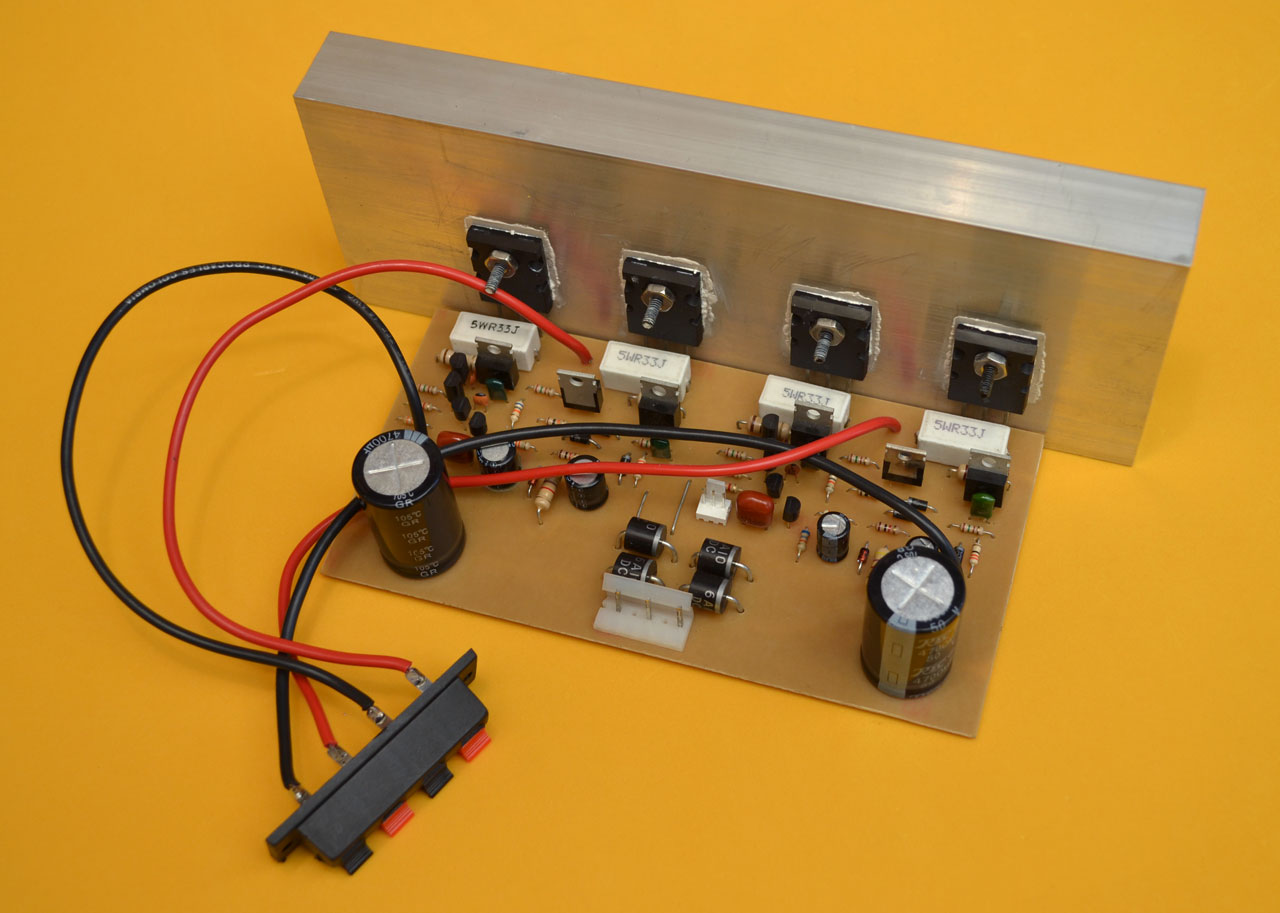
Output Transistors
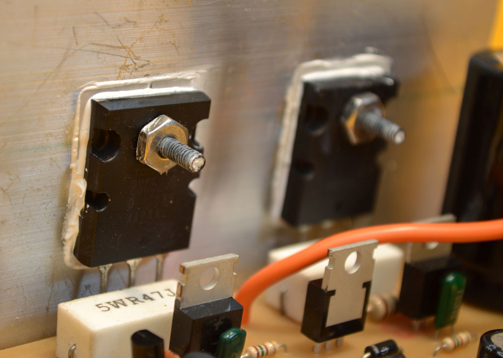
Proper Installation and Adjustment of 2SC5200 Output TransistorsTo ensure optimal performance, the 2SC5200 output transistors must be carefully adjusted and insulated from the heatsink using mica insulators, through bolts, washers, and nuts. Secure the screws tightly to facilitate efficient heat transfer from the transistors to the heatsink. Apply silicone grease to enhance heat conduction.
Important Notes on Power Transistors:
– Original 2SC5200 power transistors have low gain. Look for transistors with an hFE between 50 and 90. We recommend those with a gain of 70 or less for excellent performance.
– For 2SC3858 transistors, ensure the hFE does not exceed 50.
– When purchasing power transistors, measure the capacitance using a multimeter set to nanofarads. Touch the base with the black tip and the emitter with the red tip. A reading between 4 and 6 nanofarads indicates good quality. Values below this range may indicate poor-quality transistors prone to burning when the amplifier is stressed.
BIAS Adjustment
The BIAS adjustment regulates the current flowing through the output transistors when the amplifier is idle. Ideally, the speaker output should show zero volts when the amplifier is silent. For simplicity, this amplifier uses a preset BIAS adjustment, consisting of a 33 ohm resistor (R10) and two diodes (D2 and D3). However, it’s crucial to verify the adjustment.
To do this:
1. Connect the amplifier to the mains using a series configuration with a 60W incandescent bulb.
2. Set your multimeter to continuous voltage.
3. Measure the voltage at the point where the collector of the TIP42 meets the base of the TIP41. The reading should be between 0.6 and 0.7 volts.
4. Measure the voltage at the cathode of diode D2, where it meets the base of the other TIP42. The reading should also be between 0.6 and 0.7 volts.
If the BIAS is out of balance, it may cause:
– Crossover distortion
– Transistor overheating
– Potential burnout of the output stage
Therefore, it’s essential to verify the BIAS adjustment before connecting the speakers. If the correct voltages are not obtained, carefully check the circuit and refer to our Recommendations section.
Volume Nob

A volume nob is also known as Potentiometer. When using the amplifier with a flat frequency response, a potentiometer is required between the audio source and the amplifier. Since most audio players are stereo, we’ve used a stereo RCA female terminal.
To convert the stereo signal to monophonic:
1. Combine the left and right signal inputs using two 2.2K resistors.
2. Connect the RCA connector to the potentiometer and the 2.54mm female MOLEX connector using shielded cable.
Correct Potentiometer Placement:
1. Connect the signal from the player to terminal 3 of the potentiometer (left to right).
2. Link the center terminal of the potentiometer to the amplifier’s signal input.
3. Connect terminal 1 to ground the input connector and the amplifier. Note: If using a preamplifier, this connection is unnecessary, as the preamplifier has its own potentiometer. Simply connect the preamplifier’s signal output to the amplifier’s signal input.
The Power Supply
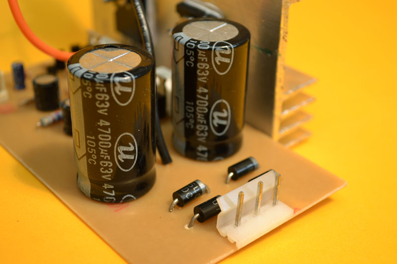
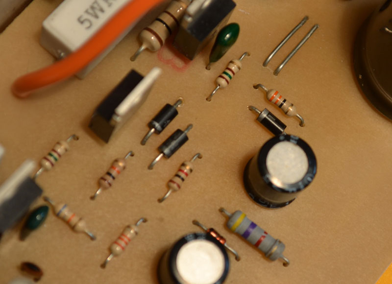
The amplifier operates on a symmetrical power source, providing positive, negative, and ground (central TAP) voltages. The central TAP serves as a reference point when the amplifier is idle. The power supply utilizes a diode bridge, formed by four 3-amp diodes, to separate positive and negative half-cycles. Two capacitors then rectify these half-cycles, converting the alternating current (AC) to direct current (DC).
Recommended Capacitor Values:
For optimal performance, use capacitors with values between 4,700uF and 6,800uF. Values below this range may result in reduced bass response at high volumes, while values above 6,800uF will only increase costs without providing additional benefits.
The Transformer

Designing a Suitable Transformer for Your Amplifier is important. When building a transformer for your amplifier, consider the intended load to ensure optimal performance:
– For 4-ohm loads, use thicker wire
– For 8-ohm loads, slightly thinner wire is sufficient
The transformer should have a central TAP with the following specifications:
– 33+33V AC configuration
– 66V AC between the ends
– 33V AC between each end and the TAP
– Minimum current rating: 3 amps
For 120V countries, use a 3.8×4 cm core and wind:
– 331 turns of 22-gauge wire for the primary winding
– 182 turns of 17-gauge wire for the secondary winding, with a central TAP soldered halfway through the turns.
Alternatively, you can wind the wire in double and complete 91 turns.
For 220V countries, wind 607 turns of 24-gauge wire for the primary winding, while keeping the secondary winding the same.
If you have any questions or concerns about building the transformer, feel free to ask.
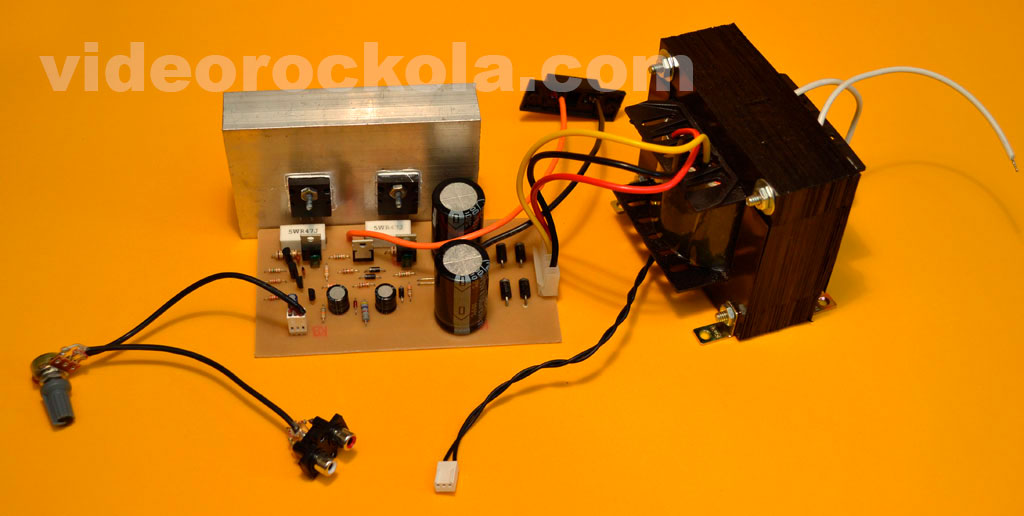
Finished amplifier
Now that our amplifier is complete and ready for installation in its cabinet, it’s crucial to perform essential measurements before powering it on. Use a multimeter set to continuity mode to:
1. Measure the AC input without connecting the transformer. The reading should indicate no connection or infinite impedance (represented by a “1” on the left side of the display).
2. Measure the speaker output. Again, the reading should show no connection or infinite impedance.
Note: During these measurements, you may briefly see numbers on the multimeter display before it shows “1” on the left. This is due to the power supply capacitors being charged by the multimeter’s voltage. The “1” on the left indicates no connection or infinite impedance.
Final Checks Before Connecting the Speaker:
Once all measurements are confirmed correct, connect the amplifier to the mains using a series circuit with a light bulb. Never connect it directly to the mains.
Verify the following:
– The series light bulb should not illuminate.
– Set your multimeter to DC voltage and measure the output: it should read 0 volts.
– Measure the channels: the voltage should be around 0.7V.
– Check the voltage of the power source after the capacitors.
If these measurements are accurate, you can proceed to connect the speaker and a signal source to test the amplifier. However, let’s review some additional important measurements before proceeding.
Measurements
WARNING ! Before powering up an amplifier for the first time, conducting thorough measurements is a must. This precautionary step is vital, as assembly errors can lead to circuit damage or malfunction, emphasizing the need for careful verification.
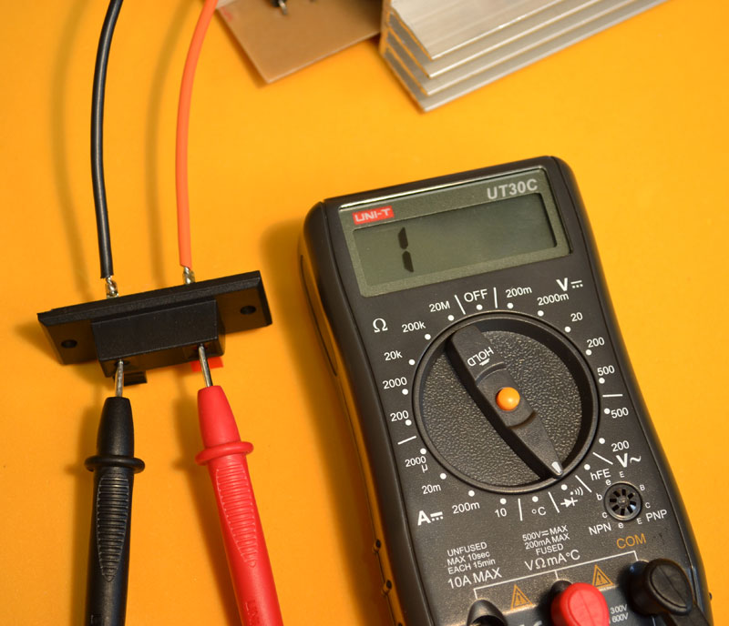
Cold Measurements: Verifying the Amplifier Before Power-On With the amplifier assembled and carefully inspected for soldering, component placement, and circuit board integrity, perform cold measurements to ensure the circuit is safe to power on. Begin by checking the speaker output:
1. Set the multimeter to continuity mode.
2. Place the black probe on the ground pin and the red probe on the positive output pin.
3. Verify the measurement reads infinity (∞) or displays a “1” on the left side. Note: Temporary readings during capacitor charging are normal.
4. Reverse the probes and confirm the measurement still reads infinity.
For incorrect measurements: (shorts or low impedance) indicates a potential issue:
1. Inspect each output transistor for defects.
2. Verify the printed circuit board tracks for any damage or shorts.
3. If using a Zobel network, check its integrity.
By performing these cold measurements, you’ll help ensure the amplifier’s safety and functionality before applying power.
Verifying Transistor-to-Heatsink Isolation:
 Before connecting the amplifier to the mains, ensure there’s no continuity between the output transistors and the heatsink. If continuity exists, it can cause transistor failure when powering on the amplifier.
To check:
1. Set the multimeter to continuity mode.
2. Touch one probe to the heatsink and the other to the collector of each transistor (usually the center pin).
3. Verify the measurement reads “no continuity” or infinity (∞), indicated by a “1” on the left side.
If continuity is detected:
1. Inspect the transistor’s insulator and replace it if necessary.
2. Check if the screw is making contact with the transistor’s back. Adjust or replace the screw as needed.
3. Repeat the measurement to ensure isolation between the transistor and heatsink.
This crucial check helps prevent potential damage to the output transistors when powering on the amplifier.
Verifying Power Input Integrity
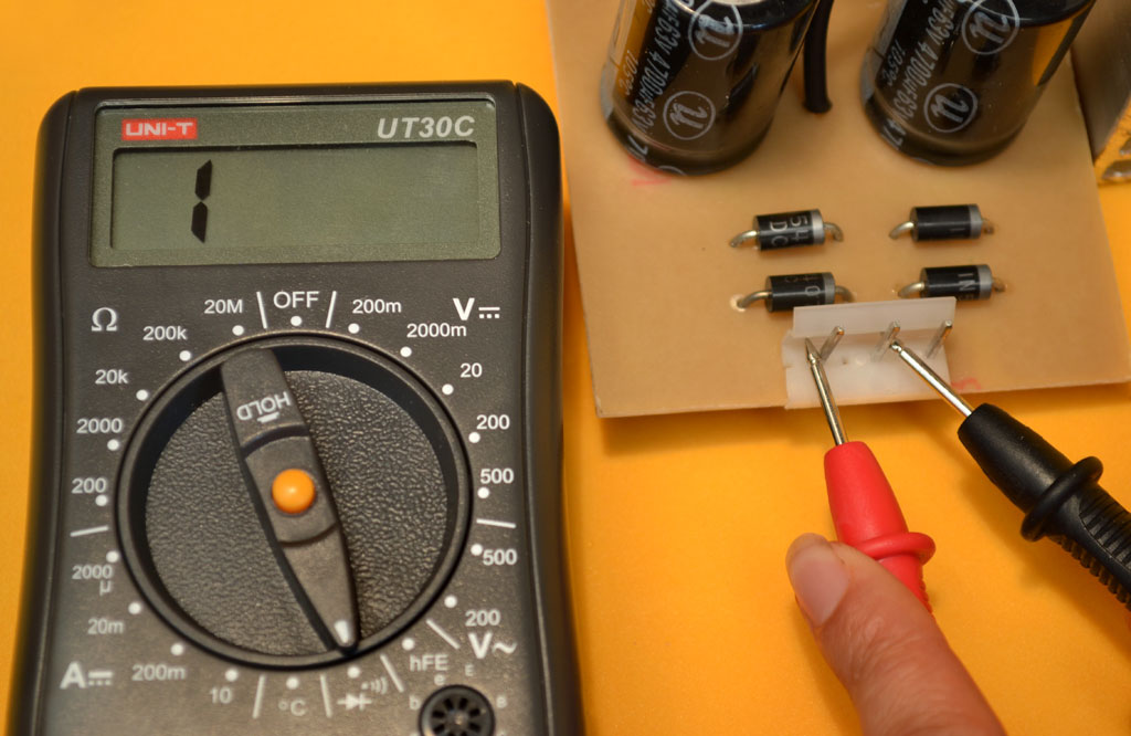
Before connecting the transformer, inspect the power input section to ensure there are no faults. This check helps identify potential issues with:
– Short circuits between power supply tracks
– Defective rectifier diodes
– Shorted power supply capacitors
To perform the check:
1. Set the multimeter to continuity mode.
2. Place one probe on the ground point (where the transformer’s central TAP will connect) and the other probe on one of the power supply pins.
3. Verify the measurement reads “no continuity” or infinity (∞), indicated by a “1” on the left side. Note: Temporary readings during capacitor charging are normal.
4. Reverse the probes and repeat the measurement between ground and the other power supply pin.
In both cases, the multimeter should not show any impedance or continuity. If it does, inspect:
– Each rectifier diode for defects
– Power supply capacitors for shorts
– Printed circuit tracks for damage or shorts
– Transistors for potential shorts
Resolving any issues detected during this check will help ensure the power supply operates safely and efficiently.
Connecting the Amplifier Safely
After verifying the correct measurements, connect the amplifier to the mains using a series circuit with a light bulb. Never connect it directly to the mains.
The series circuit serves as a protective testing mechanism, allowing you to safely test circuits or devices without risking damage. If a short circuit occurs:
– The bulb will illuminate.
– If the circuit is functioning correctly or open, the bulb will remain off or glow very faintly.
These precautionary step helps prevent potential damage to the amplifier or other components.
Connecting the Series Circuit and Interpreting Results
Attach the alligator clips of the Series Circuit to the transformer’s input terminals. Observe the bulb’s behavior:
– If the light illuminates fully, it indicates a short circuit in the amplifier. Immediately disconnect it and inspect:
– Printed circuit tracks
– Each component
– If the light glows halfway, it suggests excessive current draw. Potential causes include:
– Insufficient transformer capacity
– Short circuit in the differential pair stage
– Incorrect BIAS settings
Investigate further by:
– Measuring the hFE of each A1015 transistor
– Verifying the condition of D2 and D3 diodes in the BIAS regulation
– Checking the 33 ohm resistance value
– If the light remains off or glows very faintly, proceed with caution and perform voltage measurements (hot measurements).
Verifying Speaker Outputs with Power Applied
With the amplifier powered on, re-test the speaker outputs to confirm they’re functioning correctly.
To do this:
1. Switch your multimeter to DC voltage mode.
2. Connect the black probe to ground and the red probe to the speaker output.
3. Check that the reading shows zero volts (0V).
If you obtain a non-zero voltage reading, it may indicate a problem such as:
– Short circuit between tracks
– Defective transistor
– Faulty component
Carefully inspect the printed circuit board. In some cases, you may need to remove the transistors to
Measuring Power Supply DC Voltage
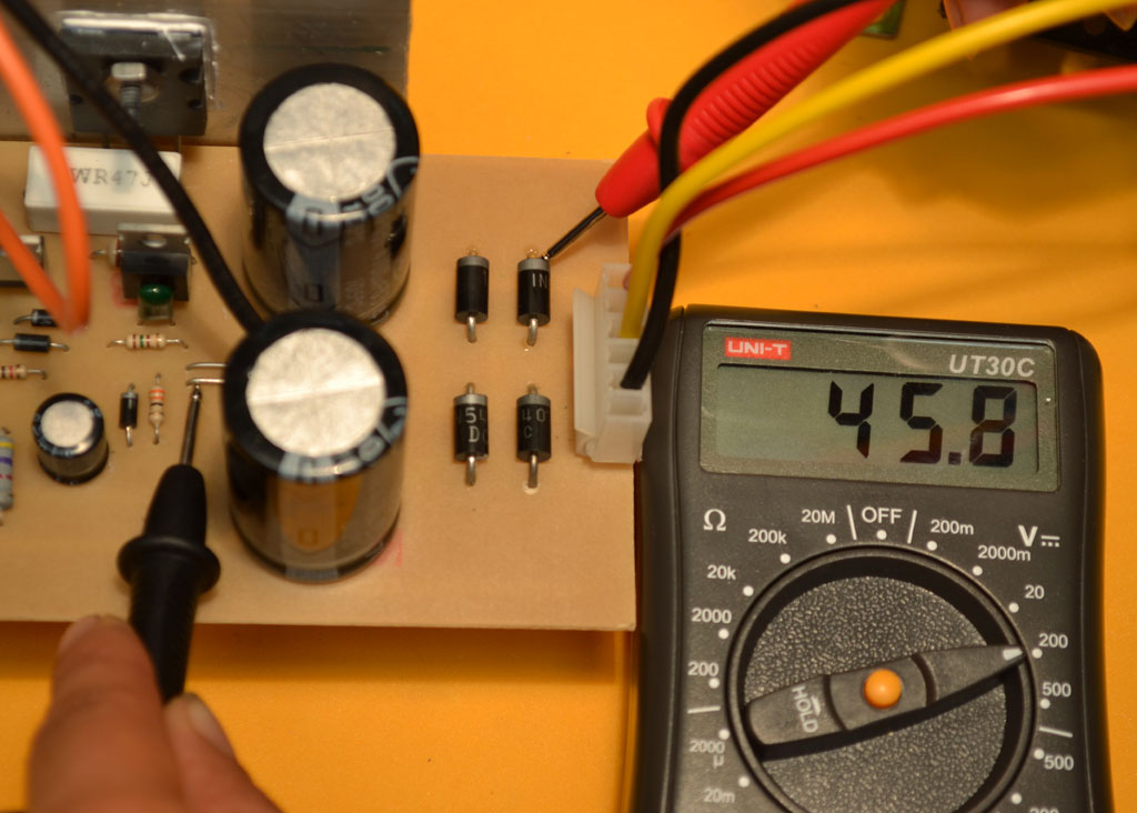
To measure the DC voltage output of the power supply:
1. Set the multimeter to DC voltage mode.
2. Place the red probe on the cathode of any positive half-cycle diode.
Expected Reading:
For a 33x33V AC transformer, the rectified DC voltage output should be approximately +/-45V DC or slightly higher. In this example, the measured positive voltage is 45.8V DC.
Troubleshooting:
If the measurement is incorrect, inspect:
– Power supply diodes
– Power supply capacitors
– Printed circuit board and its traces
Refer to our Tutorial section for further guidance.
Measuring Negative Voltage Rectification
 Next, measure the negative voltage rectified by the power supply:
1. Keep the multimeter on the DC voltage scale.
2. Place the red probe on the anode of any negative half-cycle diode.
The rectified negative voltage output should be approximately -45V DC.
Troubleshooting:
If the measurement is incorrect, inspect:
– Diodes
– Power supply capacitors
– Printed circuit board and its tracks
Voltage Symmetry Check:
The difference between the positive and negative voltage readings should not exceed 0.4V. If the voltages are not symmetrical:
– Check for defective power supply capacitors
– Verify resistors are correct
– Inspect for shorts between tracks
In this example, the voltage difference was only 0.1V, indicating symmetrical voltages.
Verifying Differential Torque Regulation Stage

To confirm the differential torque regulation stage is functioning correctly:
1. Set the multimeter to DC voltage mode.
2. Place the black probe on ground and the red probe on the cathode of the zener diode.
Expected Reading:
The voltage reading should match the zener diode’s value, which can range from 18V to 24V. In this example, a 23V zener diode is used, resulting in a measured voltage of 22.9V.
Troubleshooting:
If the expected voltage is not present:
– Check the zener diode for faults
– Verify the limiting resistor (R2) and other accompanying components
– Double-check the printed circuit board version and component placement
Remember to always verify the specific zener diode value used in your circuit.
Measuring the Differential Pair’s Resting Point

A crucial measurement is taken at the junction of the two emitters of the A1015 transistors (Q1 and Q2). Note that the voltage reading here will not match the zener diode’s voltage.
To measure:
1. Set the multimeter to DC voltage mode.
2. Place the black probe on ground and the red probe on the junction of the two transistors.
Expected Reading:
The voltage reading should be approximately 0.6-0.7 volts, indicating the amplifier is at its correct resting point.
Troubleshooting:
If the measured voltage exceeds 0.8 volts DC:
– Suspect a faulty component, starting with the 33K resistor (R3).
– A faulty R3 can allow excessive voltage to pass from the regulation stage to the differential pair, destabilizing the amplifier.
Verifying Proper BIAS Adjustment

The final crucial measurement is to confirm the BIAS is correctly adjusted. Incorrect BIAS adjustment can lead to:
– Distortion due to frequency crossover
– Excessive overheating
– Potential burning of output transistors
To avoid these issues, make this measurement before connecting the speakers.
Measurement Procedure:
1. Set the multimeter to DC voltage mode.
2. Place the black probe on ground and the red probe on the cathode of diode (D2), where it connects to the base of TIP42 (Q7).
Expected Reading:
The voltage reading should be between 0.5 and 0.6 volts.
Troubleshooting:
If the measurement is incorrect:
– Review previous checks
– Verify the A1015 transistors, which should have an hFE of approximately 170
– Be cautious of counterfeit A1015 transistors, which often have an hFE above 180 and can unbalance the BIAS.
Second BIAS Measurement

To complete the BIAS verification, take another measurement:
1. Set the multimeter to DC voltage mode.
2. Place the black probe on ground and the red probe on the 33 ohm resistor, where it connects to the base of TIP41 (Q6) and the collector of TIP42 (Q5).
Expected Reading:
The voltage reading should be between 0.6 and 0.7 volts DC.
Troubleshooting:
If the voltage is outside the expected range (less than 0.6V or greater than 0.8V):
– Inspect the circuit carefully
– Consider replacing the 33 ohm resistor with a 10 ohm one
– If issues persist, verify the authenticity of all transistors by measuring their hFE
– Visually inspect the printed circuit tracks for any defects
Amplifier Testing
If all previous measurements are correct, you’re ready to test the amplifier:
– Connect a speaker and an audio signal source (e.g., a music player)
– Verify the amplifier’s performance
100 watt mono amplifier test video
Spanish and English subtitles are included in the video. Simply press play and activate the closed caption button located at the bottom right of the video.
Introducing Our 200W Stereo Amplifier
Building on the success of our 100W mono amplifier version 2.0, we’ve designed a new printed circuit board featuring dual mono stages and a rectified power supply. This configuration enables the creation of a powerful 200W stereo amplifier.
Key Design Features:
– Spacious layout between output transistors, allowing for the use of 2SC3858 transistors
– Compatibility with 40+40V AC transformer for increased power and enhanced bass performance
– Alternative option: use 2SC5200 transistors with a 35+35V AC transformer
Optimal Performance:
To unlock the full potential of this amplifier, we recommend pairing it with a preamplifier, such as our 2-band or 3-band EQ preamplifier.
We’re confident you’ll find this amplifier to be a valuable addition to your audio setup.
Beyond Circuitry: Presentation Matters

Building an amplifier or device involves more than just creating a functional circuit. A well-designed enclosure and presentation are crucial, especially when it comes to marketing the product.
To showcase our amplifier, we crafted a custom cabinet that not only protects the electronics but also enhances its visual appeal. The cabinet features:
– A preamplifier with microphone and line inputs, combined with a 3-band EQ
– An MP3 player with USB input
– A recycled 37+37V AC transformer with 6A capacity, sourced from a salvaged device
– A power switch and fan on the rear panel to maintain a safe operating temperature
Attention to detail and a focus on presentation elevate our amplifier from a functional device to a polished product.
Transformer Windings and Voltage Regulation
The transformer used in this project has three windings:
1. A primary secondary winding providing 37-0-37V AC
2. An additional winding supplying 12-0-12V AC at 500mA, used for the preamplifier’s symmetrical power source
3. A 5V winding intended to power the MP3 player
However, a challenge arose: the 5V AC winding, when rectified, produced 7V DC, which was insufficient for the LM7805 regulator to deliver the required 5V regulated output. To resolve this issue, a voltage doubler was employed to convert the 5V AC to ±7V DC. By taking the ±7V DC outputs and reducing them to 5V using the regulator, a stable voltage supply for the MP3 player was achieved. This showcases an alternative application of a voltage doubler.
Powering MP3 Players: Voltage Considerations

When selecting an MP3 player, it’s essential to verify the required voltage, as it can vary. Common voltages include 5V and 12V. Failure to check the specifications can lead to damage.
You can purchase this particular players from your local electronis store or from www.alibaba.com, a Chinese website offering a wide range of players with diverse features and prices.
Connection Precautions:
– The power supply connects to the red connector, requiring careful attention to polarity to avoid instant damage from reverse connection.
– The signal cable, a shielded stereo duplex, carries the audio signal to the preamplifier while minimizing parasitic noise infiltration.
Finally A Professional-Grade Amplifier

We’re proud to showcase the completed amplifier, encased in a sturdy metal box with an electrostatic paint finish and a wooden cover wrapped in synthetic leather. Additional features include:
– Metal corners for added protection
– A handle for easy transportation
– A custom-designed front panel created in Corel Draw and printed on adhesive vinyl paper (download the Corel file here) We hope this project inspires you to create a high-quality product that can be marketed and sold. Remember to prioritize safety by installing a 2-amp fuse at the transformer input. Don’t forget to check our Tutorial section for additional guidance.
>>>Download here<<< The PDF file with all the information and the printed circuit to assemble thequasi-complementary 100 watt monophonic amplifier .
>>>Download here<<< The PDF file with information, electrical diagram, printed circuit board and bill of materials to assemble the200 watt quasi-complementary stereo amplifier .