
This 60-watts stereo audio amplifier is Incredibly easy to build and perfect for home and laptop use, offering a unique combination of small size, low cost and impressive performance.
 To take our amplifier to the next level, we can pair it with a preamplifier featuring tone controls, such as a preamp with microphone, line, and EQ input, or one with voltage-controlled volume and tone control. This combination will yield exceptional performance from the amplifier. Notably, the amplifier also delivers impressive sound quality even without tone controls, allowing for satisfactory equalization through computer software or a video jukebox. Another successful configuration we’ve tested is pairing the amplifier with a three-band EQ preamplifier, which can be built by following the instructions available here.
Materials
 To get started, let’s go over the necessary materials for this amplifier project. You’ll find a paid downloadable PDF file at the end of this article, which includes the printed circuit board layout, electrical diagram, and detailed bill of materials.
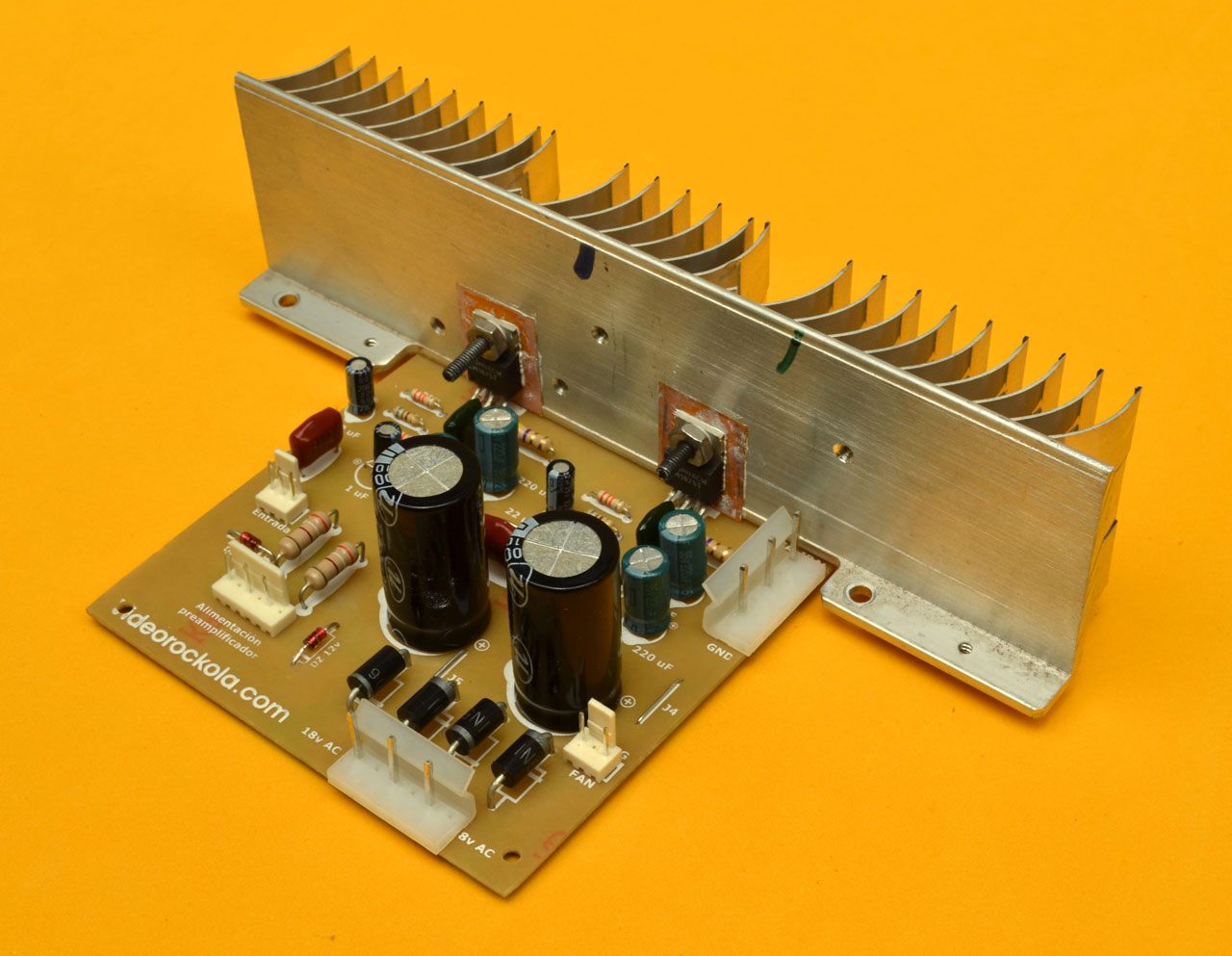
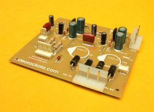
The photo illustrates the key components required for the main board assembly. Note that the transformer and cables are not shown, as they will be discussed in a subsequent section
When sourcing components, exercise extreme caution and thoroughly inspect each item. If possible, utilize a multimeter to verify their accuracy, as counterfeit components are increasingly prevalent in the market, posing a significant risk of fraud.
Placing the resistors
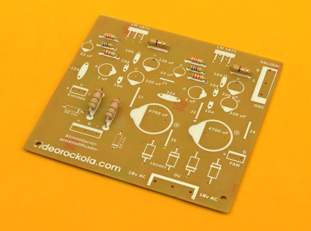 Fabricate the printed circuit board (PCB) by selecting either the ironing or silkscreen method, as described in our PCB manufacturing guide, depending on your requirements and budget constraints.
Once the PCB is ready, proceed to component placement, starting with the resistors. Ensure they are arranged in a tidy and organized manner, with precise alignment, as shown in the photo.
Note that the majority of resistors in the circuit are 1/4W, except for the 4.7 ohm resistors in the Zobel network, which require 1/2W, and the 390/470 ohm resistors used to polarize the zener diodes, which are rated at 1W.
For optimal heat dissipation and to prevent overheating, install resistors with specific spacings: 1/4W resistors should be mounted directly on the board, while 1/2W and 1W resistors require a minimum 1mm clearance above the board’s surface.
The amplifier’s gain is determined by the combined effect of the 68 ohm (R2) and 33K ohm (R3) resistors, yielding a gain of 48.5 times when calculated as 33,000 divided by 680. This gain factor represents the extent to which the signal is amplified. Furthermore, leftover resistor terminals are repurposed to create bridges or jumpers, connecting isolated tracks on the board. To maintain a tidy appearance, ensure these bridges are precisely straight. For a closer look, click on the photo.
Additional regulated source
 To accommodate a potential preamplifier, we’ve utilized an available space on the printed circuit board to integrate a regulated symmetrical power supply. This supply consists of a pair of 12-volt zener diodes and their corresponding biasing resistors. The amplifier’s DC voltage is approximately ±24 volts, which is then stepped down to ±12 volts DC by the zener diodes, providing a stable and regulated output.
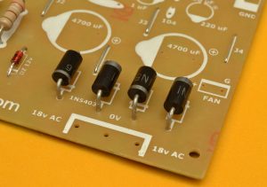 The 1N5403 rectifier diodes, rated at 3 amps, are well-suited for this application. Notably, the ‘1N54′ prefix signifies a 3-amp capacity, while the ’03’ suffix indicates a 300-volt rating. Diodes with higher voltage ratings, such as 1N5407 (700V), are also compatible, given the power supply’s relatively low 18×18 volts. The primary requirement is a minimum 3-amp handling capacity. These four diodes are strategically configured to isolate the positive and negative half-cycles of the transformer’s AC output, enabling rectification and efficient conversion to DC power.
Non-polar capacitors
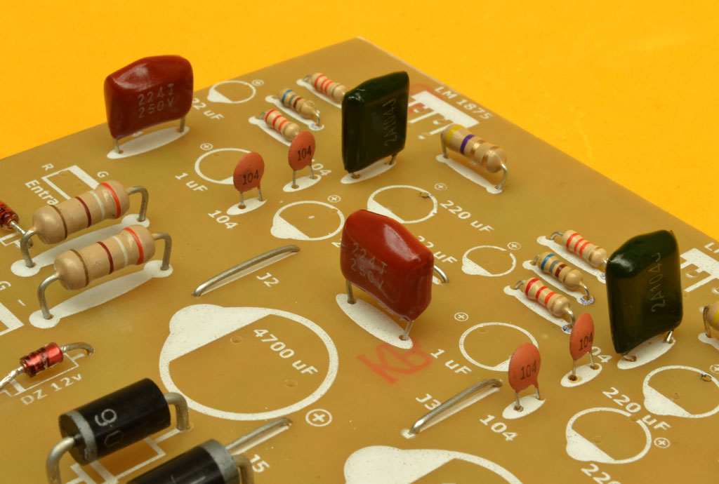 Previously, we installed polyester and ceramic capacitors, which play distinct roles in the circuit. Let’s break down their specific functions:
The 0.1 uF (104) ceramic capacitors serve as noise filters, removing unwanted “cripples” or voltage spikes from the power source. Four capacitors are used, with two assigned to each channel: one connects +Vcc to ground, and the other connects -Vcc to ground, ensuring effective noise suppression.
The two 0.1 uF (104) polyester capacitors are integral to the Zobel Network, which prevents oscillations and safeguards the circuit. In tandem with the 4.7 ohm resistors, these capacitors shield the integrated circuits from potential damage caused by reverse currents from the speaker and unwanted oscillations.
Lastly, the 0.22 uF (224) capacitors function as DC signal input decouplers, effectively blocking any parasitic DC currents originating from the player, thereby preventing them from interfering with the amplifier’s operation.
Electrolytic capacitors
 Electrolytic capacitors differ from polyester and ceramic capacitors in that they have polarity, requiring careful consideration during placement. The component mask indicates the negative pole with a bump, and the capacitor itself features a minus sign stripe.These capacitors serve various functions: 220uF capacitors filter DC current, removing unwanted ripples; 22uF capacitors provide a DC shunt to ground for the gain resistors; and 1uF capacitors act as DC input decouplers, ensuring clean power delivery
The importance of connectors
 To ensure a professional-looking amplifier, simplify final assembly, and facilitate future maintenance, we’ve incorporated connectors at key connection points. These connectors link the amplifier to external components, such as the transformer.Specifically: We’ve used large 6-pin MOLEX connectors, modified to 3-pin by removing an intermediate pin, for the speaker output and transformer input. A small 3-pin, 2.54mm connector (locally known as GP connectors in Colombia) is used for signal input. An additional 3-pin connector, with the center pin removed, is dedicated to the fan output.
Important Note: The fan output provides 24 volts DC, so it’s essential to use a 24-volt fan. If you prefer to use a 12-volt fan instead, you’ll need to add a limiting resistor in series with the fan’s positive terminal. A 100-ohm, 5W resistor can be used, but for optimal performance, calculate the resistor value using the following formula:
Vt – Vf / Af
To calculate the required resistor value, use the following formula: Total Voltage – Fan Voltage / Fan Current For instance, if you’re using a 12V fan with a current draw of 0.25A: see bellow
24V DC – 12V DC = 12V DC / 0.25 amps = 48 ohms.
To ensure optimal performance and minimize heat generation, it’s recommended to increase the calculated resistance value by 30%. This provides a safety margin and reduces the risk of overheating. Aiming for a resistor value of 68 ohms or slightly higher is ideal.
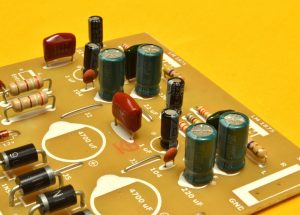
The power supply capacitors
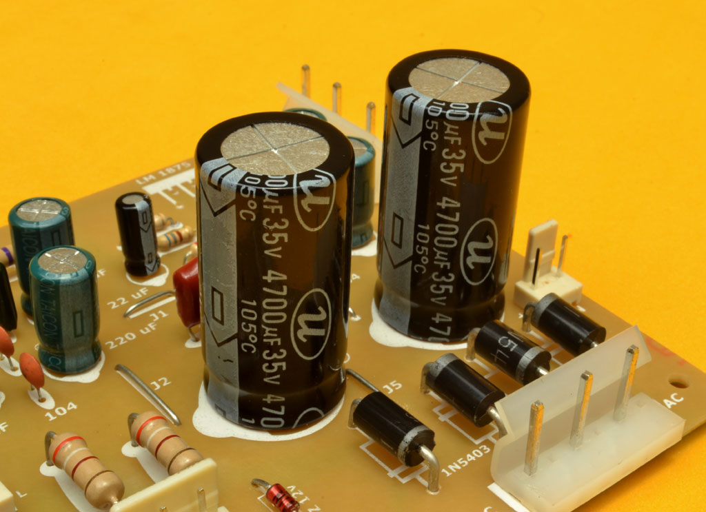 The 4700 uF electrolytic capacitors are a key component of the rectifier source, collaborating with the 4 1N5403 diodes to rectify AC current into DC current. Capacitors rated at 35 volts or higher are recommended for this configuration.
We do not necessarily need to use the TDA2050 integrated circuit. The LM1875 will also work.
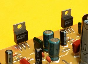 The TDA2050 is a high-performance, monolithic class AB audio amplifier integrated circuit. It delivers impressive power output: up to 35 Watts RMS into a 4-ohm speaker load and 32 Watts into an 8-ohm load, with minimal distortion.However, after successfully building numerous amplifiers with the TDA2050 over two years, I encountered a concerning issue: counterfeit versions began circulating, making it challenging to obtain authentic components.In response, I transitioned to using the LM1875, which, despite being rated for 20W per channel, has yielded comparable performance in my experience. Moreover, I’ve found the LM1875 to offer superior sound definition and clarity.
The heat sink
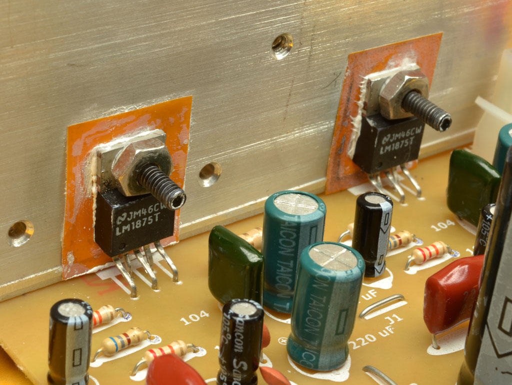
To ensure reliable operation and prevent overheating, it’s crucial to use a high-quality heatsink, and in many cases, an additional fan (cooler) is also recommended. Integrated circuits generate significant heat while amplifying sound, so never power on your amplifier without properly securing the heatsink first.When mounting the integrated circuits to the heatsink, use screws with nuts and ensure electrical isolation with mica insulators and insulating bushings (also known as “grommets”). These small plastic pieces prevent the screw from making contact with the heatsink and the integrated circuit, which is essential since the back of the IC is connected to the negative voltage (-Vcc). Without proper isolation, short circuits can easily occur when the heatsink comes into contact with ground or the common pole.For this amplifier, a transformer with an 18×18 volts AC output and a minimum current rating of 3 amps is required.
 To construct the transformer for this amplifier, a 2.8 cm x 3.5 cm core is used. Since the public network outlet voltage is 120 to 220v volts, the primary winding requires 514 turns of 24-gauge wire. The secondary winding needs 154 turns of 18-gauge wire countries which provide 120v. Due to the central TAP, it’s essential to stop halfway through the secondary winding turns (73 turns) and solder an output cable. Then, the remaining 73 turns can be wound. Alternatively, you can wind the 73 turns with doubled wire, as demonstrated in our transformer-building video. Adjustments for countries with 220V public network voltage, the primary winding requires 942 turns of 26-gauge wire (according to the AWG table). The secondary winding turns and wire gauge remain unchanged.
Recycling Transformers:
A cost-effective and eco-friendly option is to repurpose transformers from old equipment. When using a recycled transformer, identify the input and output cables by locating the primary and secondary winding terminals.
Testing the Transformer: Use a series circuit with a 100W incandescent or halogen bulb to test the transformer. Connect the series circuit on mains power and quickly connect and disconnect the aligetor probes to the suspected primary transformer terminals. When the series circuit doesn’t turn on, you’ve located the primary winding. Then, use a multimeter on the AC voltage scale to measure the other terminals and identify the central TAP, determining the transformer’s output voltages.