
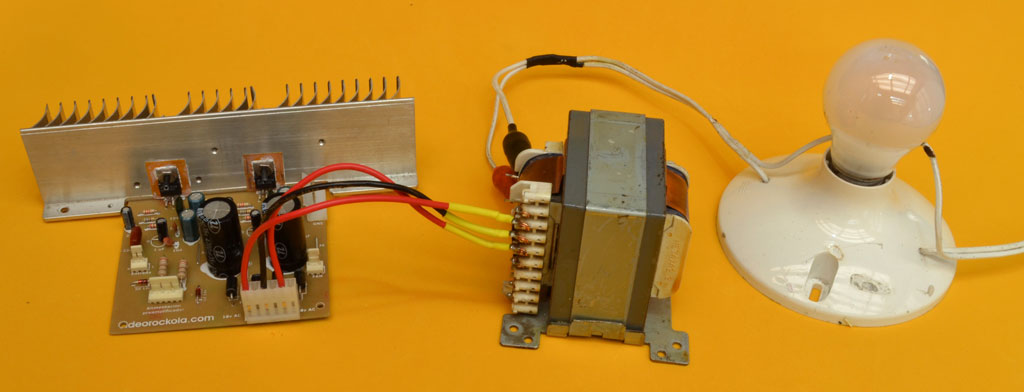
Amplifier almost ready
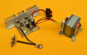
Let’s take a look at the completed amplifier, ready for installation in its cabinet. As you can see, it features a recycled transformer, which I sourced from a junkyard. Although its original application is unknown, I suspect it came from a mini component sound system. This transformer provides 17×17 volts and 4 amps, which, despite being slightly under the recommended voltage, still yields a great sound quality.Using a recycled transformer is an excellent alternative for those who prefer not to build their own. Additionally, the heatsink is also recycled, making this project not only cost-effective but also environmentally friendly. By repurposing these components, we’re reducing electronic waste and promoting sustainability.
How to install a volume potentiometer on an amplifier
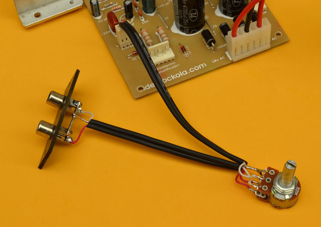
The most common way to use an amplifier is with a preamplifier with tone controls. This allows you to control the volume and equalization of the sound. However, amplifiers are sometimes used with a flat response, as in recording studios. To use the amplifier with a flat frequency response, you must place a double potentiometer between the signal source and amplifier. This is to control the volume and the amplifier gain from going out of control.
Wiring diagram of a volume potentiometer
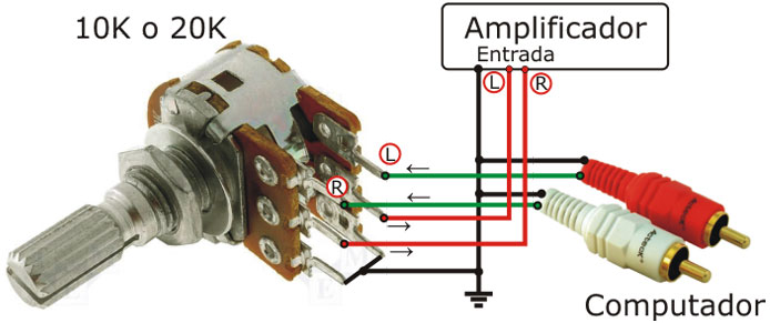
To properly install a volume potentiometer:
1. Solder the two left terminals together.
2. Connect the ground wire to these unified terminals.
3. Connect the line input cables from the input connectors and amplifier to the potentiometer.
4. Solder the signal cables going to the amplifier to the two center terminals of the potentiometer.
5. Finally, solder the cables from the signal input connectors to the remaining two terminals of the potentiometer
Amplifier with additional preamplifier
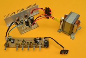
To achieve a specific frequency boost, consider pairing your amplifier with a preamplifier featuring tone controls. The combination of our 60-watt amplifier with a 3-band EQ preamplifier, line input, and mixed microphone connection produces excellent sound quality. If you don’t require a microphone input, our 2-band and 3-band preamplifiers are recommended alternatives. We’ve tested these options and were satisfied with the results.
What speakers to use?
For optimal performance, we recommend pairing this amplifier with speakers that have a power handling capacity of 100W to 150W and an impedance of 8 Ohms. The speaker size can be chosen based on personal preference, but we suggest using speakers between 8 and 12 inches in size.
Measurements
IMPORTANT: Before powering on the amplifier, conduct thorough measurements to ensure error-free assembly and prevent potential damage to the circuit.
To verify the power supply input:
1. Set your multimeter to continuity mode.
2. Measure between each transformer cable pin and the center pin/center tap.
3. Initially, you may see some numbers due to capacitor charging, but the reading should quickly stabilize to infinity (displayed as “1” on the left).
4. Reverse the leads and repeat the measurement.
If you obtain any reading or impedance, it may indicate a short-circuited track or faulty component. Inspect each component and examine the printed circuit tracks under light for any issues. Read our Recommendations section .
If the measurement checks out, you can connect the amplifier to the mains power using a series circuit. NEVER CONNECT IT DIRECTLY TO THE POWER SOURCE.
The series circuit is a safety testing setup that allows you to test circuits or devices without risking damage or burnout. Here’s how it works:
– If the device is short-circuited, the bulb will light up.
– If the circuit is not short-circuited or is open, the bulb will remain dark.
– If the bulb lights up slightly, it may indicate a minor issue.
For more information on using a series circuit for testing, refer to our article on the Test Board.
The series circuit
Measuring speaker outputs
Next, measure the speaker outputs while the amplifier is powered on and current is flowing. Set your multimeter to the DC voltage scale and:
1. Place the black probe on ground and the red probe on the right output.
2. Verify that the reading shows 0V.
3. Repeat the measurement between ground and the left output.
If any voltage is detected on either output, it may indicate a short circuit between tracks or a faulty component. Inspect the printed circuit board carefully. In some cases, it may be necessary to remove and replace the integrated circuits to rule out any defects.
Measuring the regulation stage for the preamplifier
To verify the regulation stage of the preamplifier, measure the output voltages at the connector. Follow these steps:
1. Set your multimeter to the DC voltage scale in this case it is 20V Scale because we are measuring below that scale so it is important to know that, to secure your multimeter but there are other multimeters which do not require to do that because the range has already been set as DC or AC regardless of the value to be measured .
2. Place the black lead on the center pin of the connector (ground/GND).
3. Measure the voltage by placing the red lead first on the left pin and then on the right pin.
The expected voltage readings are:
– Between the center pin (GND) and the left pin: +12V
– Between the center pin (GND) and the right pin: -12V
If these voltage readings are incorrect, troubleshoot by:
1. Verifying the limiting resistors are functioning properly.
2. If issues persist, replace the zener diodes.
Once you’ve completed these checks, your amplifier is ready for testing.
Download PDF File bellow
IT IS IMPORTANT that before you start building the amplifier circuit found in the PDF file, you read the written article thoroughly and watch the video. In many cases it is not enough to just view the PDF file.
>>>Download here<<< The PDF file with the schematic diagram, printed circuit board and bill of materials, for the creation of the super economical 30w amplifier .
>>>Download here<<< The PDF file with the diagram, bill of materials and PCB of the 30W amplifier , 15W monophonic version with TDA2030 , which you can use with our Pre-amp .