
Learn how to make a very affordable 15W per channel stereo amplifier .
There are often times when we require a compact amplifier that is still powerful enough to adequately fill a room. Additionally, we may be limited by a tight budget and a lack of expertise in electronics. For these reasons, we present an affordable stereo audio amplifier that provides 15 watts of power per channel.
This amplifier is perfect for smaller areas and has been successfully tested, producing satisfactory results. Its flat response allows for sound equalization through the software on the computer or the device you are using, whether it’s a tablet or an MP3 player.
Easy to make
 This stereo amplifier is ideal for newcomers due to its user-friendly design and low cost. It incorporates two TDA2030 integrated circuits, which are monolithic Class AB circuits that can produce up to 15W of output power with an 8 Ohm load. The 5-pin TDA2030 circuit delivers a high output current while maintaining low harmonic distortion. Furthermore, it includes an automatic short circuit protection system that limits power dissipation to safeguard the output transistors, ensuring consistent performance. It also has a standard thermal shutdown feature. All of these advantages come at a very reasonable price and are readily available.
Diagram in schematic
.png)
The schematic diagram shows that this is an amplifier configured in a non-inverting mode. This means the signal is input through the non-inverting terminal (+). Consequently, the audio signal that goes into the amplifier will come out with the same polarity it had when it entered.
Printed circuit board
A printed circuit board (PCB) is created from a plastic material (such as bakelite) or fiberglass, which is coated with copper. The design of the printed circuit is transferred onto the copper using various methods, including ironing or silk-screening techniques. While these methods are the most common, there are more advanced techniques available today, primarily used for mass production. In this instance, we utilized the silk-screening method to apply the component mask and solder mask. However, the video linked at the end of this article showcases a PCB manufactured using the ironing technique. Ultimately, we can confirm that regardless of the method used to create the printed circuit, it will function correctly as long as it adheres to the necessary standards and is executed with care and precision.
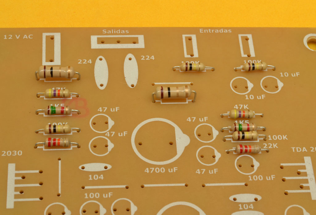 Once the printed circuit board is prepared, the first electronic components we typically install are the resistors. In this instance, all the resistors are rated at 1/4W, with the exception of two 1-ohm resistors, which are rated at 1/2W. The primary role of the resistors is to limit current; however, their function can vary based on their placement, how they are interconnected, and the surrounding components. For instance, the 100K resistor (R1) connected in parallel to the signal input is responsible for determining the input impedance. If this resistor is replaced with one of a higher value, it could increase the noise level, but if a lower resistor value, such as 33K, is used, the volume will start to diminish. The amplifier’s gain or sensitivity is determined by the 47K resistor (R5) and the 1.5K resistor (R3), also referred to as 1K5. By dividing 47K by 1.5K, we find the gain to be 47,000 / 1,500 = 31.333 times amplification. To increase the gain, we can replace the 1.5K resistor with a 1K resistor. Conversely, to decrease the gain, we can substitute the 47K resistor with a 33K resistor. In any case, the circuit is already configured with suitable values to provide a good gain without introducing excessive distortion.
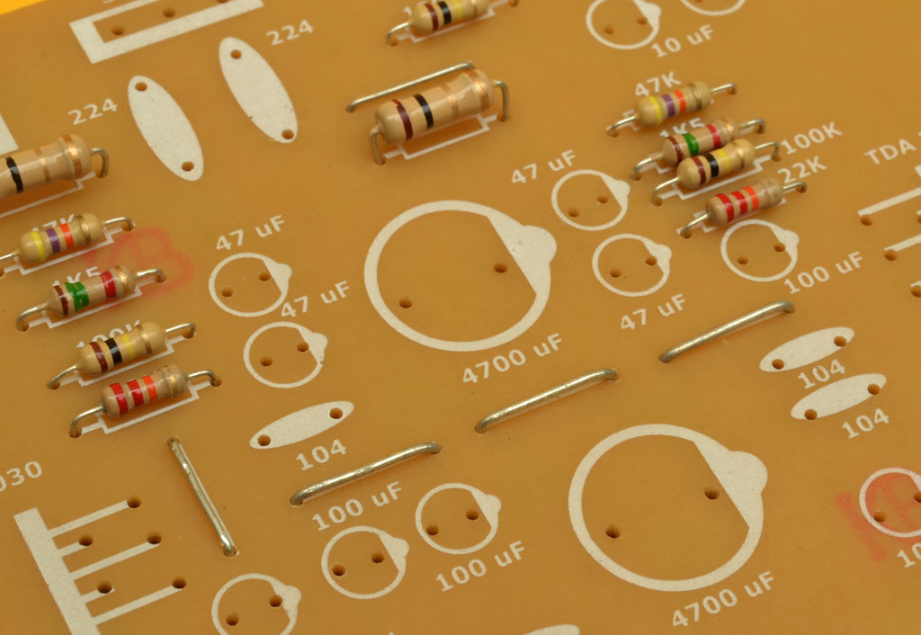 Finish the circuit by crafting bridges or jumpers from leftover resistor leads. These connections allow current to flow between previously unconnected points on the PCB. For a professional finish, make sure the bridges are straight and neatly positioned, as illustrated. A well-organized build is essential to ensuring the project works as intended.
Half-wave source
The TDA2030 operates on a dual power source, also referred to as a symmetrical power supply. To optimize economy, the amplifier’s power supply design incorporates a voltage doubler, which converts AC to DC and increases the voltage. This efficient design eliminates the need for a transformer with a center tap, allowing a simple 12V AC, 4A transformer to power the amplifier effectively.
Electrical diagram
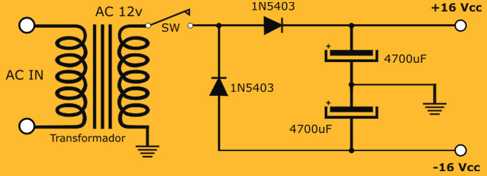
The diagram illustrates the transformer’s output, where one terminal is grounded and the other is connected to a pair of diodes and a switch for turning the amplifier on and off. Since the transformer delivers alternating current (AC), which oscillates at 60Hz, the positive and negative half-cycles must be separated. This is achieved by the two 1N5403 diodes, each rated at 3 amps. The diodes are configured to direct positive half-cycles to one capacitor, producing an output voltage of 15-16V DC, while negative half-cycles pass through the other diode to the second capacitor, generating a negative voltage of -15 to -16V DC. This setup effectively creates a symmetrical voltage from a simple transformer.
Important Note: This amplifier is not designed for automotive use, as its symmetrical power supply requires an AC input. Applying a DC voltage from a car battery would render the voltage doubler ineffective, making it impossible to achieve a symmetrical output. For car audio applications, consider our dedicated Car Amplifier project, which can be powered directly from a 12V source or battery.
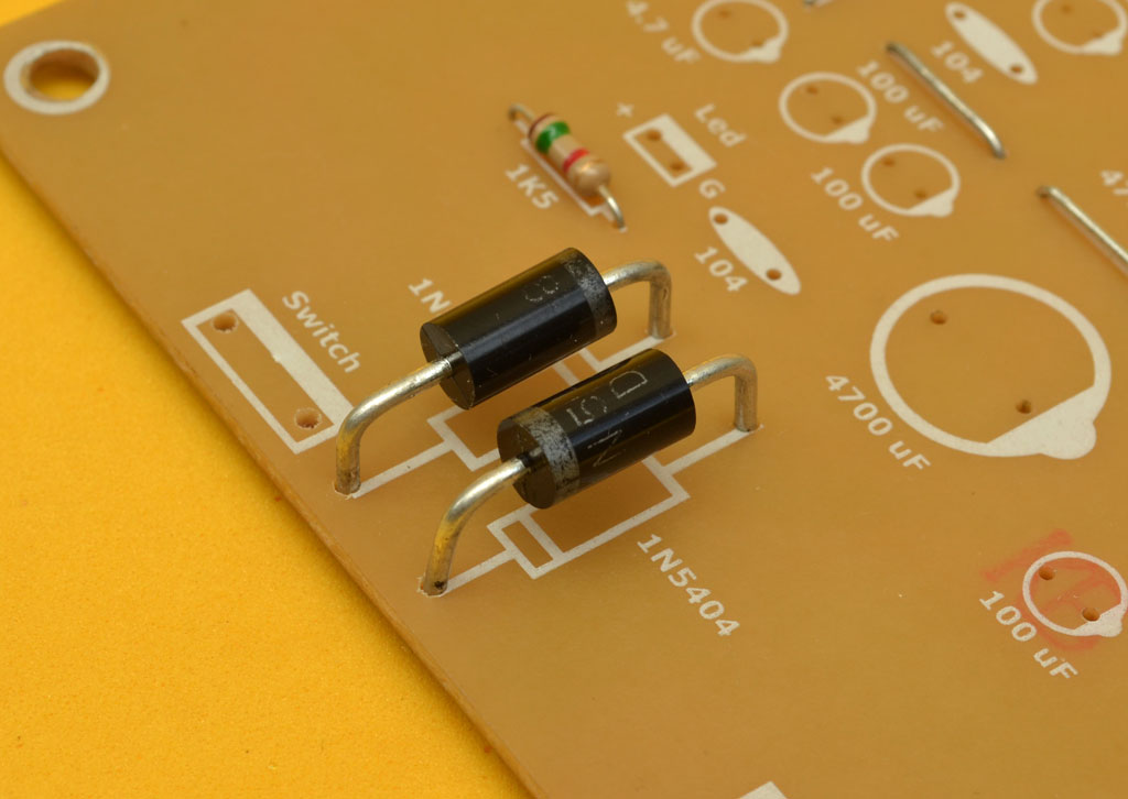 Examine the installed power supply diodes, noting that they should be slightly elevated from the board to facilitate heat dissipation. A minimum rating of 3 amps is required, with compatible options including 1N5401 to 1N5408. Although these diodes vary in peak voltage rating (100V to 800V), this distinction is irrelevant in this 12V-powered amplifier. The critical factor is ensuring the diodes can handle at least 3 amps to prevent overheating and potential failure.
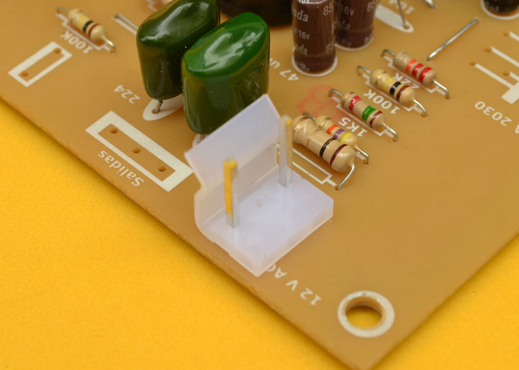
 The capacitors shown are 0.22uF (224) polyester film capacitors, which form part of the Zobel network along with the two 1-ohm resistors. The Zobel network, also known as an oscillation damper, safeguards the output ICs from potential backflow currents from the speakers and oscillations. While ceramic capacitors can be used, polyester capacitors are preferred due to their higher precision and ability to withstand greater voltage peaks.
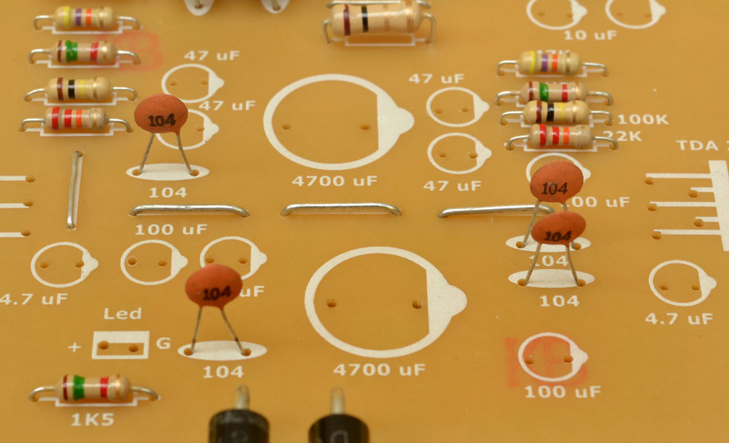 The ceramic capacitors in this amplifier serve to filter out unwanted ripples in the current. These ripples are parasitic currents that can contaminate the DC current, resulting in audible noise or hum in the audio output. To mitigate this, 0.1uF (100nF or 104 in Japanese code) capacitors are connected in parallel to the DC power input, on both the positive and negative voltage lines. These capacitors can be either ceramic or polyester and are non-polarized.
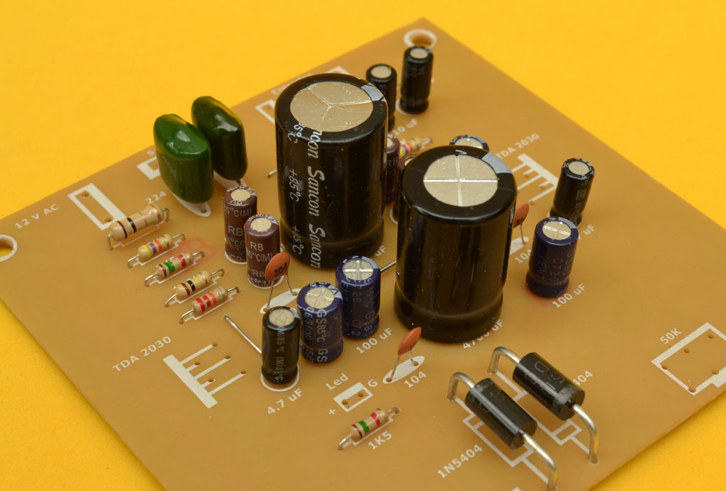 Electrolytic capacitors are recognizable by their cylindrical shape and distinct polarity. New capacitors typically have a longer positive terminal and a white stripe with a negative sign. It’s crucial to install these capacitors correctly, as reversing their polarity can cause circuit malfunctions, overheating, and even explosions. To ensure accurate placement, refer to the component mask provided in the PDF file at the end of this article.
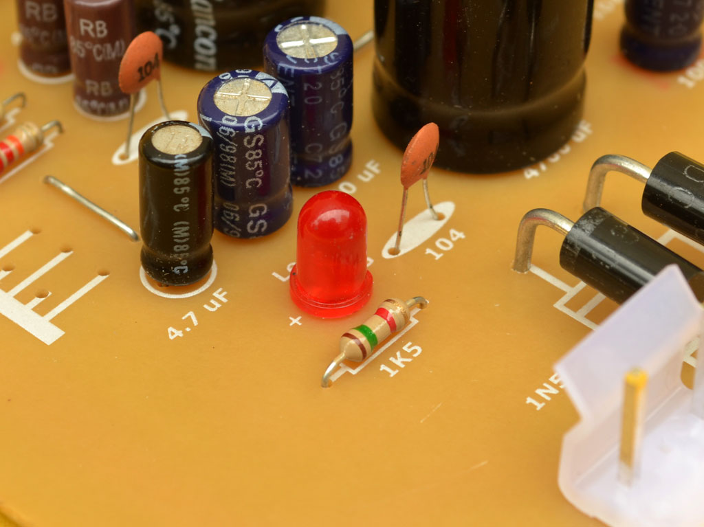 The LED serves as a power indicator, showing whether the amplifier is on or off. It can be mounted directly on the circuit board or remotely using a connector and cable, allowing it to be placed on the front panel of the enclosure. In this case, we’ve mounted it on the board to minimize cabling, but in the accompanying video, we’ve demonstrated remote mounting. The adjacent 1.5K resistor is the LED’s current-limiting resistor, which prevents excessive current from flowing when powered by the 15V DC output of the voltage doubler. Typically, a standard red LED operates at 2.8V and 0.02A, so when using a higher voltage and current, a limiting resistor is essential. To calculate the required resistance, use the formula: Total voltage minus LED voltage, divided by LED current. divided by the LED amps 16 volts – 2.8 volts of LED = 13.2 volts, / 0.02 = 660 ohms, but since the resistor got a bit hot, we raised it to 1.5K, and in the process guaranteed a long life for the LED.
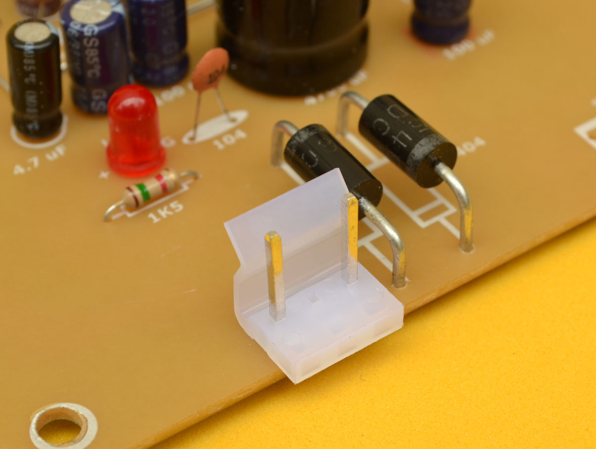 The connector shown in the photo is a 3-pin MOLEX-type connector with a 3.96mm spacing, but we’ve removed the center pin. This connector is linked to the power switch. If you prefer not to use a switch, you can simply omit the connector and replace it with a bridge or jumper, connecting the two holes. This is a useful option when integrating multiple circuits, such as an MP3 player or preamplifier, which may require separate transformer windings. In these cases, it’s often necessary to locate the switch at the transformer input rather than the output.
AC power Connector
 The second 3-pin MOLEX connector (3.96mm spacing) receives the voltage from the transformer. Since the transformer outputs AC voltage, polarity is not a concern. Important note: Beginners in electronics often confuse AC transformers with DC adapters. However, a DC adapter is not suitable for this amplifier, as it requires an alternating current (AC) input to function correctly. The voltage doubler circuit relies on AC input to produce the symmetrical voltage required by the amplifier to operate.
Volume Control
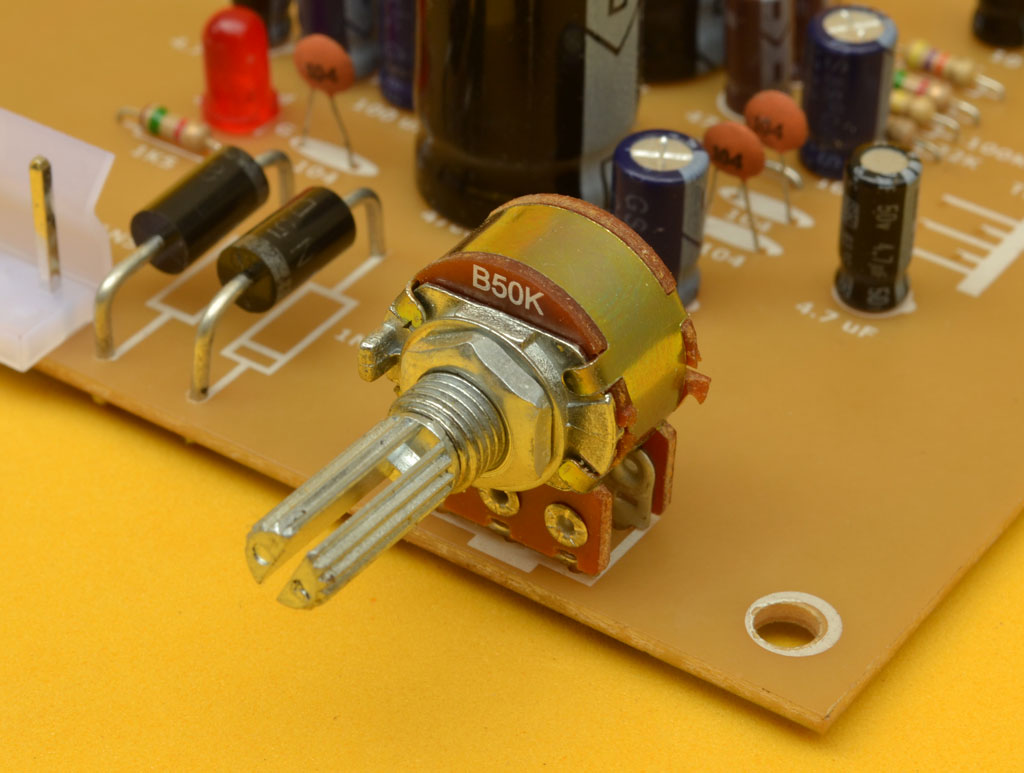 Since this is a stereo amplifier, the volume control is a dual potentiometer, consisting of two separate potentiometers within a single housing, sharing the same rotational axis. The recommended value for this potentiometer ranges from 10K to 50K. It’s worth noting that lower-value potentiometers (e.g., 10K) tend to produce a sharper response, but with lower noise levels, whereas higher-value potentiometers (e.g., 150K or above) may exhibit a softer response. However, within the recommended range, the differences are negligible, and only become noticeable with significantly lower or higher values.
Audio inputs and outputs
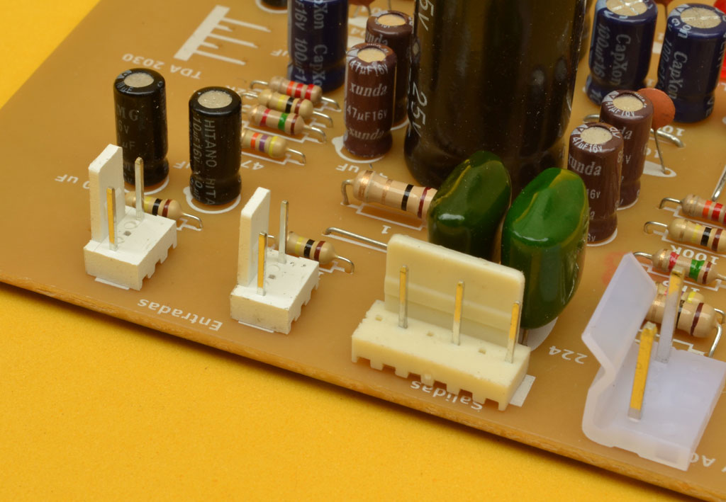 The three smallest connectors are locally known as GP connectors, but are officially referred to as 2.54mm connector leads headers when purchasing online. The two leftmost connectors, originally 3-pin, had their center pins removed and serve as the audio signal inputs. The pins closest to the board’s edge are grounded, while the opposite pins receive the left and right audio signals, one per connector. The third connector, initially 6-pin, was modified to 3 pins, spaced farther apart, and is used for speaker output. In this connector, the center pin is grounded, and the outer pins connect to the left and right speakers, respectively.
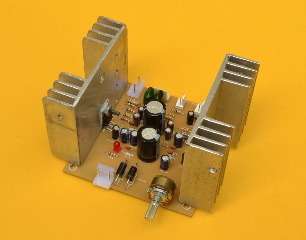
The Heatsink
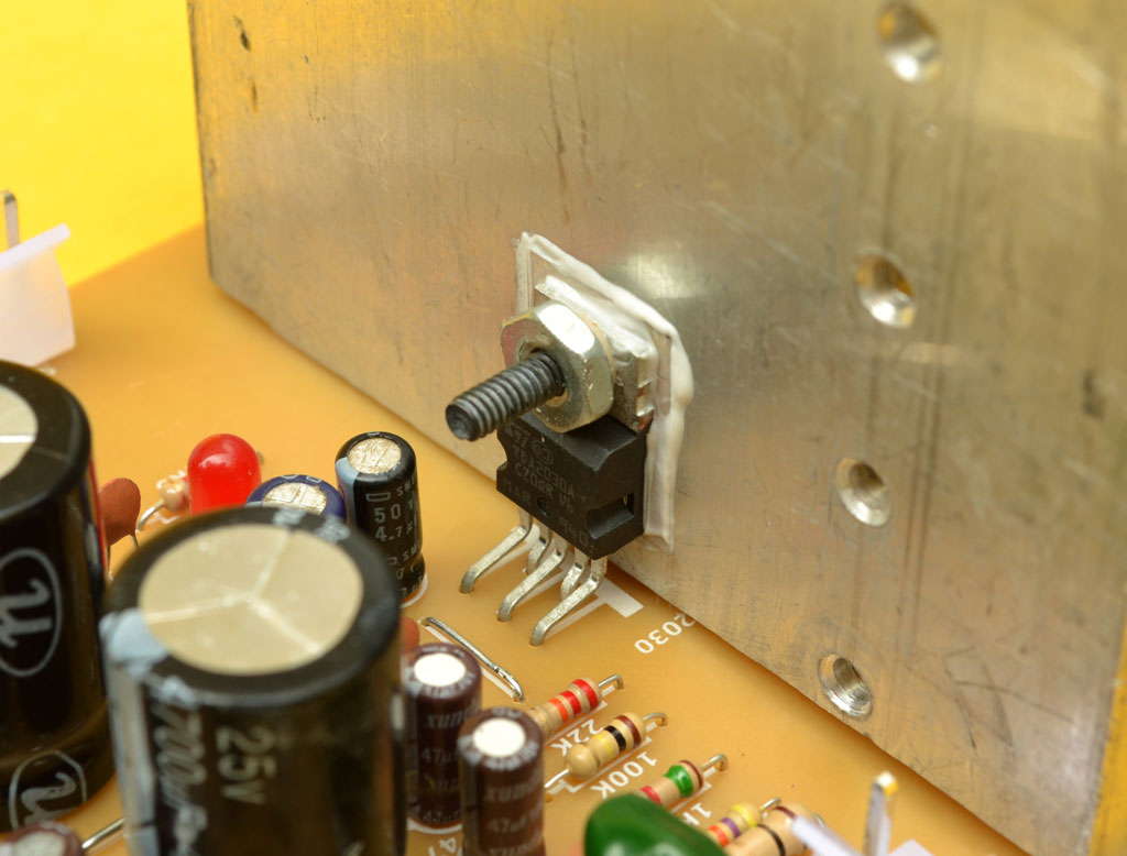 Using heatsinks for integrated circuits is crucial, as neglecting to do so can lead to overheating and damage. Unfortunately, some individuals underestimate the importance of heatsinks and only realize their mistake after the integrated circuits have burned out. Since the TDA2030 integrated circuit’s backside conducts a negative voltage, it’s essential to isolate each heatsink to prevent potential short circuits when assembling the amplifier. Typically, heatsinks are attached to the grounded case, making proper insulation vital to avoid fatal consequences. To isolate the integrated circuit correctly, use mica insulators and insulating bushings (also known as “wall passers”) on both sides of the screw. This means placing one bushing on the front of the integrated circuit and another on the back of the heatsink. After installation, verify the insulation using a multimeter set to the continuity scale. Place one probe on the heatsink and the other on the metal part of the integrated circuit. If the multimeter shows any reading (even a “1” on the left), recheck the insulation.
 In addition to the amplifier itself, the input and output cables must also be constructed. For the signal input cable, you’ll need a shielded stereo duplex cable, a pair of 3-pin 2.54mm female GP or MOLEX connectors, and a female RCA connector. Alternatively, some users prefer to use a 1/8″ stereo plug to connect the amplifier directly to an iPod, PC, or MP3 player. Regardless of the connector type, it’s essential to respect the input and ground pins and carefully study the connection method. For the speaker output cables, a thicker gauge wire (typically 16 or 14 AWG) is used. A 6-pin female connector is attached to the amplifier end, while a dual-banana speaker connector is attached to the other end. For a detailed walkthrough of building these cables, please refer to the accompanying video at the end of this article.
 The optimal power switch for this project is a three-pin, two-position switch. However, since a six-pin, two-position switch was available, we utilized it, connecting only one side. To connect one of these switches correctly, attach one wire to the center pin and the other wire to one of the end pins. Switches come with varying voltage and ampere ratings. For this project, a switch with a minimum ampere rating of 3 amps is sufficient. The voltage rating is not a concern, as most switches have a minimum rating of 120 volts, and only 12 volts will be passing through it.
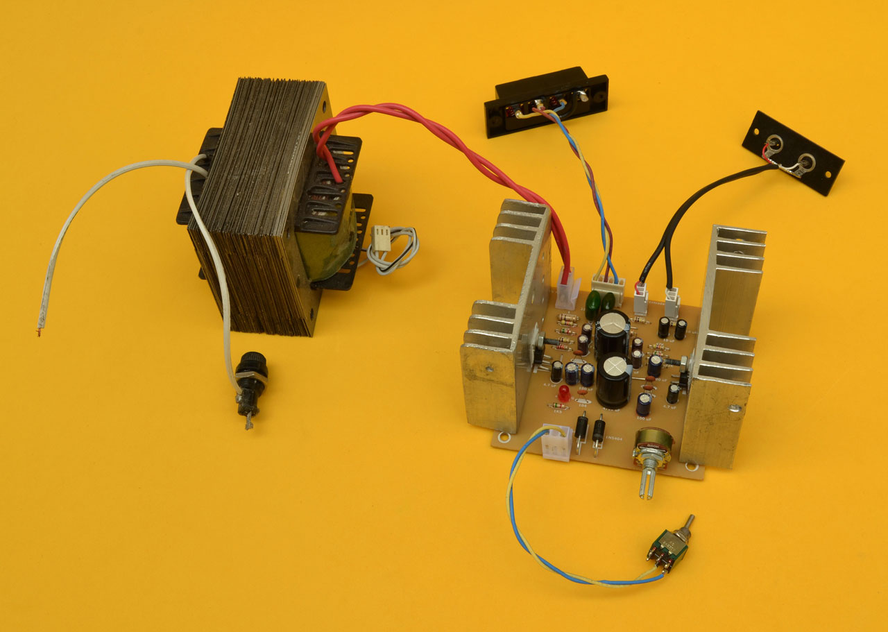
The transformer
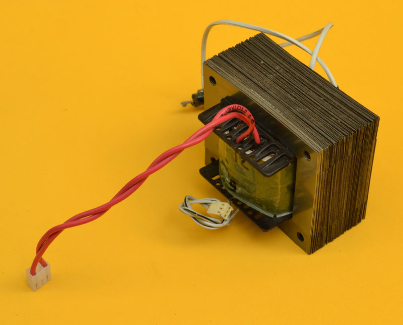 For the transformer construction in this amplifier project, we utilized a core measuring 2.8 cm x 3.5 cm. Considering Colombia’s public network voltage of 120V, we wound 515 turns of 24-gauge wire for the primary winding and 52 turns of 18-gauge wire for the secondary winding. For countries with a 220V public network, 942 turns of 26-gauge wire (according to the AWG table) are required for the primary winding, while the secondary winding remains the same. Additionally, we included a separate 9V winding, intended for powering an MP3 player with a USB input that requires 5V. This allows us to create a regulated 5V power source, stepping down the 9VAC to 5VDC.
Now that the amplifier is complete, let’s move on to the final checks before connecting the speakers. First, carefully clean the printed circuit board’s underside, particularly around the tracks, using a toothbrush and thinner to remove any remaining particles or solder splinters. Inspect the board thoroughly, holding it up to a light source, to ensure there are no shorts or collisions between tracks or solder joints.
Before proceeding with measurements, consider the speaker selection. This amplifier is compatible with speakers rated at 60W MAX (approximately 20-25W RMS) or higher, with an impedance of 8 Ohms. Note that the “MAX” rating refers to peak power for a short duration. For optimal performance, we recommend using 8- to 10-inch speakers, with tweeters rated at 15W or higher. The speaker size is ultimately up to personal preference.
Measurements
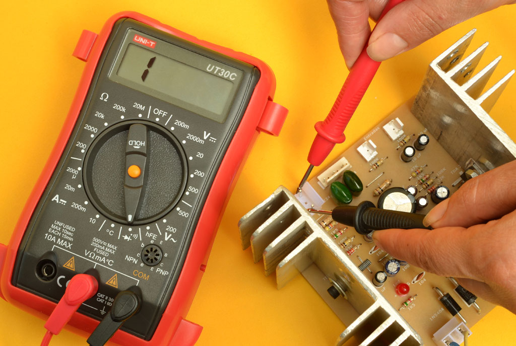 Note that during measurement, you may initially see some readings while the capacitors charge with the voltage from the multimeter. This is a normal phenomenon. Allow a few seconds for the reading to stabilize and display infinity, indicating that the capacitors have fully charged and the circuit is functioning as expected.
To measure the speaker outputs, use the multimeter in continuity mode. Measure between each output terminal and ground, and verify that the reading shows no continuity (i.e., no shorts). You may briefly see some numbers on the screen, but they should quickly settle to “1” on the left side of the display, indicating that there is no unwanted connection between the output and ground.


If the measurement reveals any impedance at the output, it may indicate a problem, such as a short circuit between tracks, a faulty or weak solder joint, a defective integrated circuit associated with that output, or even a counterfeit TDA2030 chip. In this case, please refer to our Recommendations section for further guidance.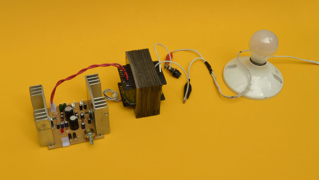 Once the cold measurements are confirmed correct, connect the amplifier to the mains power using a serial circuit as a protective measure. NEVER CONNECT IT DIRECTLY. The serial circuit is a simple electrical circuit that allows safe testing of devices without risking damage from overloads. If the amplifier is short-circuited, the bulb will light up fully. If the amplifier is not shorted or is open, the bulb will not light up or will be very dim. Connect the alligator clips of the serial circuit to the transformer’s two current input wires. If the bulb lights up fully, it indicates a short in the amplifier, requiring a thorough check of the tracks and components. If the bulb lights up at half brightness, it suggests a current draw, possibly due to issues with the transformer’s construction or adjustment. In any case, the bulb will consume the current, protecting the amplifier. If the bulb doesn’t light up or lights up very slightly, proceed with voltage measurements (hot measurements). IMPORTANT: Use a bulb with a power rating of 30W or maximum 40W, as a higher rating may not provide adequate protection. To verify the voltage rectifier or half-wave source is functioning correctly, set the multimeter to the DC voltage scale. Place the black probe on the ground (center pin of the speaker output connector) and the red probe on the cathode of the first diode. The measured voltage should be between +15V and +16V DC.


Next, we need to verify the negative voltage. Place the black probe on the ground and the red probe on the anode of the second diode. The measured voltage should be between -15V and -16V DC. It’s essential to note that the positive and negative voltages must be symmetrical. For example, if the positive voltage measures 15.1V, the negative voltage should be -15.1V. If the voltages are not symmetrical, there may be an issue, and you should recheck the diodes and capacitors in the power supply.
To measure the hot speaker outputs, set the multimeter to the continuous voltage scale. Measure the outputs by placing the black probe on the ground and the red probe on each speaker output. This test checks the condition of the TDA2030 chips and ensures there are no shorts on the output tracks.


When measuring the outputs, you should read 0.0 volts. If any voltage is present, it may indicate a problem, such as a defective or counterfeit integrated circuit, or a short circuit between the tracks. In this case, re-examine the circuit.
If all measurements are correct, you can now connect the speakers and test the amplifier. Start with a low volume and, if everything works as expected, remove the serial circuit and connect the amplifier directly to the mains power. Gradually increase the volume to a reasonable level. If the integrated circuits heat up quickly, it may be due to inadequate heatsink size, insufficient speaker cable length, or speakers with an impedance lower than 8 ohms. Verify the speaker impedance using a multimeter set to the 200-ohm scale to ensure they are 8 ohms and in good condition.
Download PDF File bellow
IT IS IMPORTANT that before you start building the amplifier circuit found in the PDF file, you read the written article thoroughly and watch the video. In many cases it is not enough to just view the PDF file.
>>>Download here<<< The PDF file with the schematic diagram, printed circuit board and bill of materials, for the creation of the super economical 30w amplifier .
>>>Download here<<< The PDF file with the diagram, bill of materials and PCB of the 30W amplifier , 15W monophonic version with TDA2030 , which you can use with our Pre-amp .