
Learn How To Build a 90w Amplifier Using TDA7294
This versatile monophonic amplifier is compatible with a range of devices, such as electric guitar and bass preamplifiers, low-pass filters, and more.
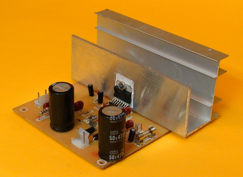 Introducing a 90W monophonic audio amplifier, versatile enough to be used in various projects. If you’re interested in creating a monophonic and stereo 90W amplifier, you’ll find a link to a paid stereo and flat response version at the end of this article. We’ve designed a PCB for this amplifier, complete with an integrated power supply. Notably, we’ve employed a voltage doubler, eliminating the need for a transformer with a central tap. Additionally, the downloadable paid PDF file at the end of this article includes an alternative PCB design featuring a symmetrical power supply.
A notable advantage of this sound amplifier is its simplicity, achieved with a minimal number of components that are not only inexpensive but also easy to find. The TDA7294 integrated circuit is a popular choice, particularly among video jukebox manufacturers in Colombia, due to its excellent balance of power, affordability, durability, and robustness against rough handling.
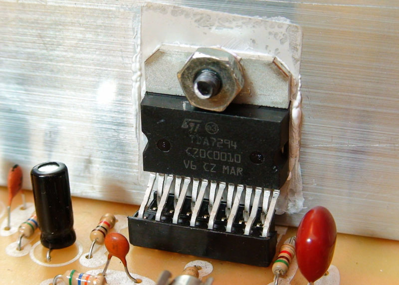
The TDA7294 is a 15-pin monolithic integrated circuit designed for Hi-Fi audio applications. As a Class AB audio amplifier, it offers a wide operating voltage range and high current handling capability, allowing it to drive 4 Ohm or 8 Ohm loads efficiently, even with poorly regulated or high-ripple supply voltages. Additionally, the TDA7294 features a muting function that utilizes a half-wave voltage to eliminate power-on/off noise.
TDA7294 Features
Here are some key features:
- High Output Power: Capable of delivering up to 100W of music power.
- Wide Voltage Range: Operates within a range of ±40V, making it suitable for various power supply conditions.
- Low Distortion & Noise: Ensures high-quality audio output with very low harmonic distortion and noise.
- Muting/Standby Functions: Built-in muting and standby functions simplify remote operation and eliminate switching noise.
- Short Circuit Protection & Thermal Shutdown: Includes protection mechanisms to ensure safe operation.
Electrical characteristics Circuit tested with voltage = ± 35V , RL= 8 Ohms , GV = 30 dB ;
Rg = 50 W; Tamb = 25 ° C, f = 1 kHz.
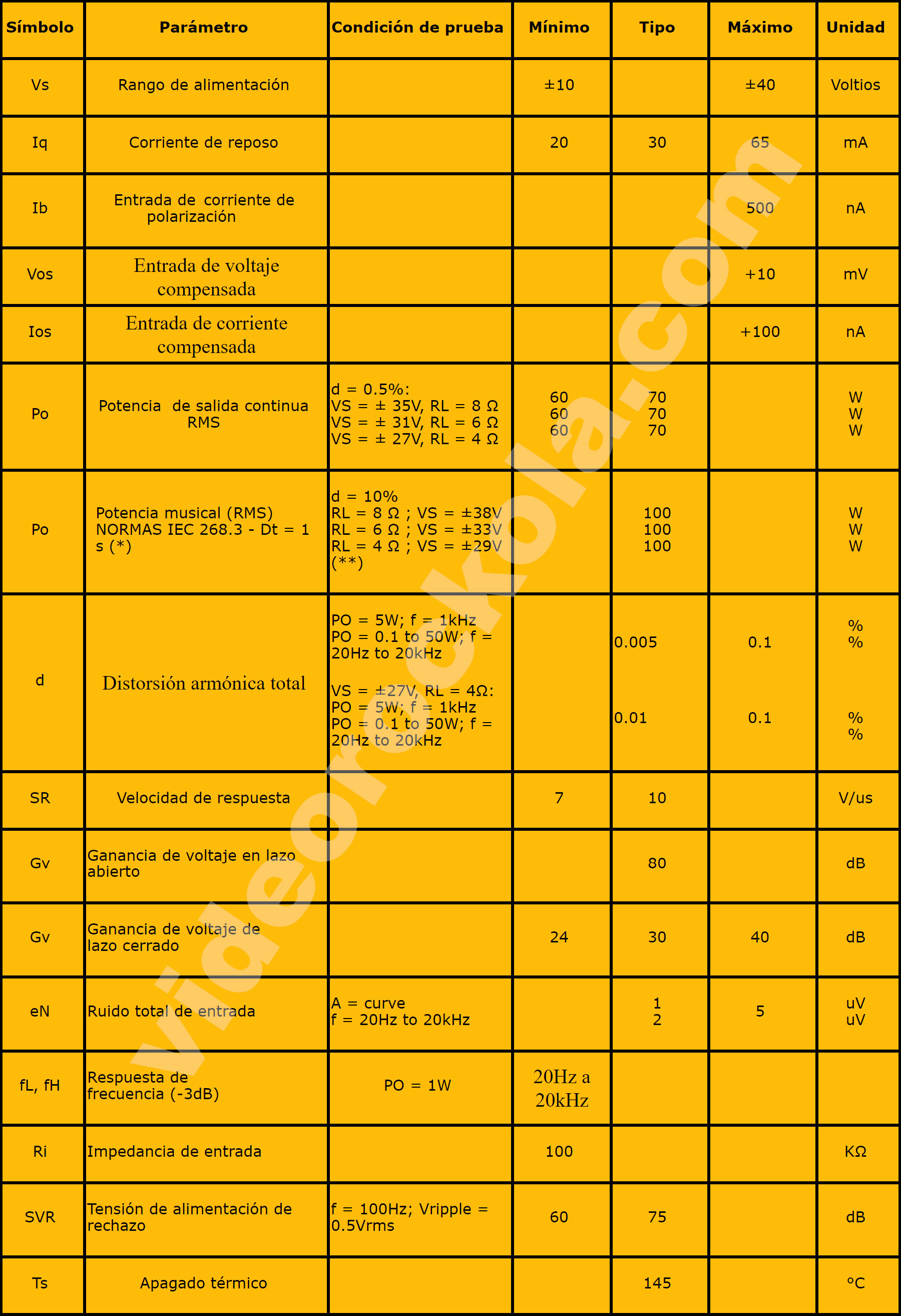
NOTE : (*): MUSIC POWER ; It is the maximum power that the amplifier is capable of producing, through the nominal load resistance (without taking into account non-linearity)
one second after the application of a sinusoidal input signal of 1 KHz frequency.
NOTE : (**): limited by the maximum allowable current.
The recommended values for external components are shown in the schematic diagram in the PDF file. The modifiable values in the following table can help you customize your circuit. Components not listed in the table should not be modified.
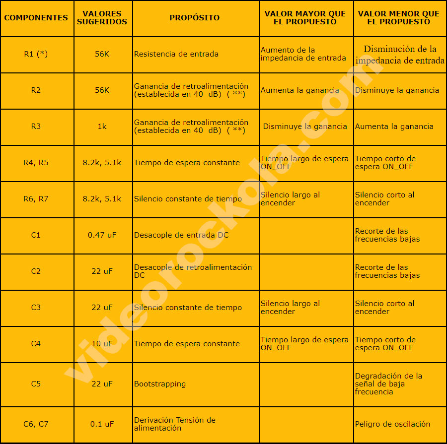
( * ) r1 = r3 of pop optimization
( ** ) The feedback gain must be greater than or equal to 24 decibels (db).
Zobel’s Network
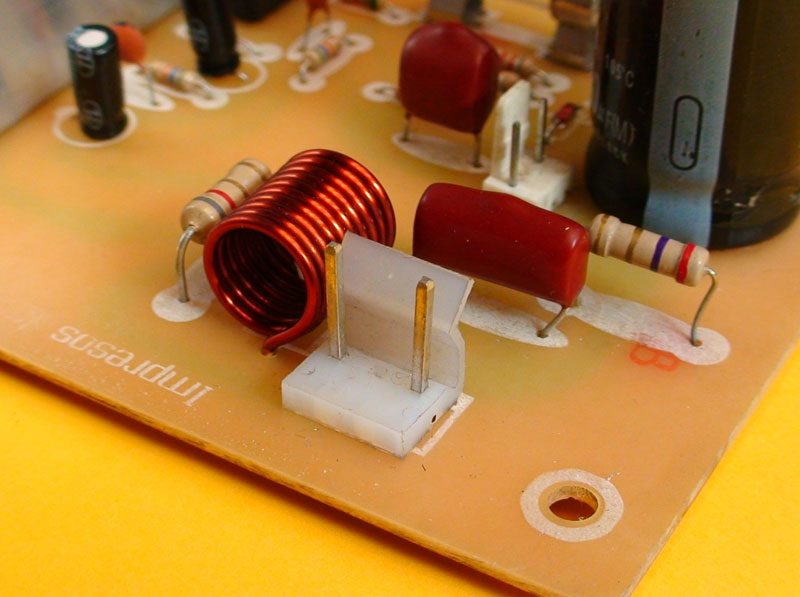
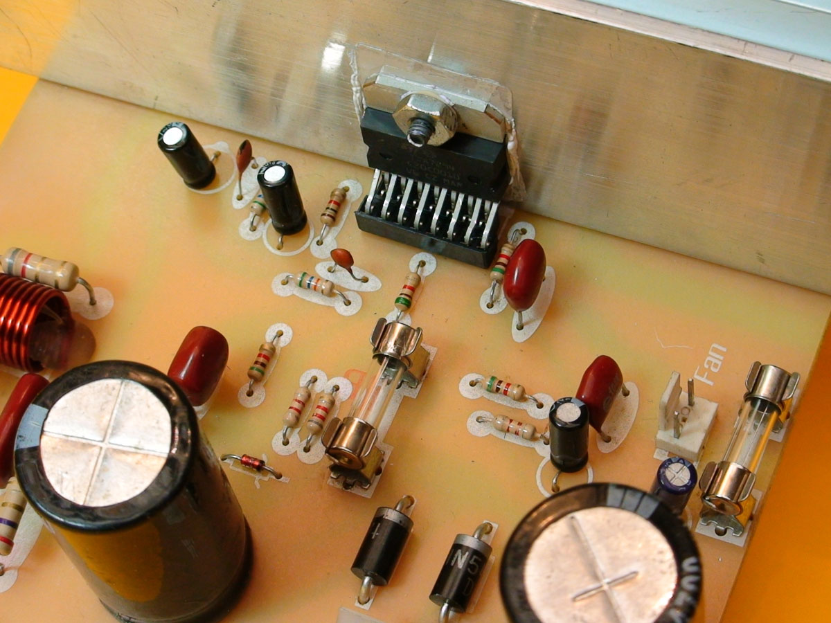
The Zobel network plays a crucial role in safeguarding the TDA7294’s output from reverse currents that may be sent by the speaker, as well as preventing high-frequency oscillations. This network consists of four components: A 0.1 μF capacitor (104) and a 2.7 Ω resistor, connected in series between the output and ground. An 8.2 Ω resistor and a 5 μH coil, connected in series with the speaker and in parallel with each other. To create the coil, follow these steps:
– Use 18-gauge copper wire (1.024 mm diameter).
– Wrap the wire evenly around a 3/8 drill bit 11 times.
– Trim excess wire and straighten the coil’s legs to achieve the desired shape.
Note: The order of the 104 capacitor and 2.7 Ω resistor does not matter, as they are connected in series without any intervening components.
Protecting The PCB
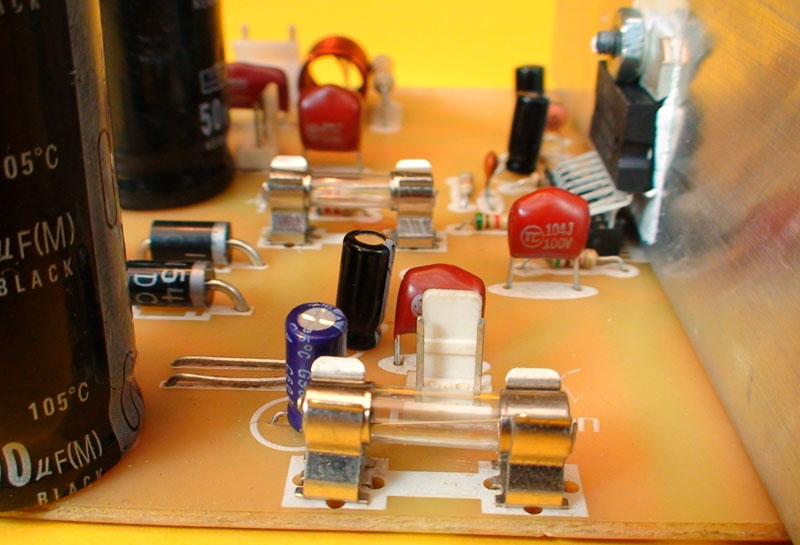
To prevent damage to the printed circuit board in the event of an amplifier short-circuit, we’ve incorporated two fuse holders with 5-amp fuses. These fuses safeguard the circuit by interrupting the current flow in both +Vcc and -Vcc lines when a short occurs, thereby preventing further damage. When selecting fuses, keep in mind that:
– High-value fuses may not blow in time to prevent damage during a short circuit.
– Low-value fuses may not support the circuit’s operating current.
We recommend using fuses with a rating between 5 and 6 amps for optimal protection.
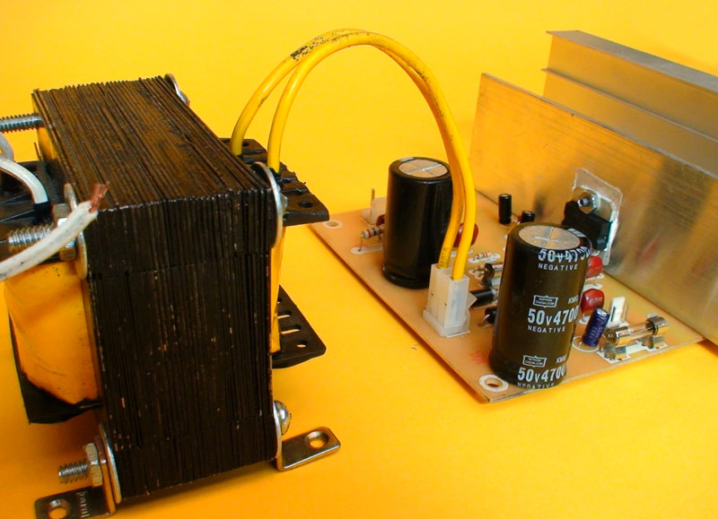
Voltage Doubling Source
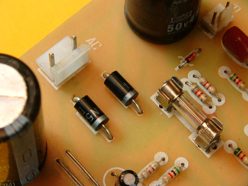
When building an amplifier, the first component to acquire is typically the transformer. Since it’s often easier to obtain a standard transformer without a center tap, we’ve incorporated a voltage doubler circuit to create a symmetrical power source. This circuit provides positive and negative voltages, as well as a ground point, without requiring a center-tapped transformer. The voltage doubler consists of two 1N5404 diodes and two 4,700 μF capacitors. The diodes separate the positive and negative half-cycles, while the capacitors rectify the corresponding half-cycles based on their position in the circuit. In essence, one diode directs positive half-cycles to one capacitor, while the other diode directs negative half-cycles to the other capacitor.
Stand By and Muting Functions
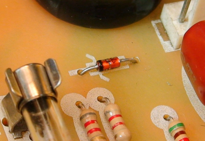
The 1N4148 diode is packaged in a glass SMD format and features a distinctive black band that identifies the cathode (negative terminal) and distinguishes it from the anode (positive terminal). This diode boasts high-speed switching capabilities, transitioning between high and low impedance states in just 4 nanoseconds. In this specific application, the 1N4148 diode directs positive half-cycles to pin 9 of the TDA7294, which controls the standby function. The current then passes through several resistors and also reaches pin 10, responsible for muting. For added control over the muting function, you can insert a switch in series with the diode, effectively creating a power switch. This modification eliminates the annoying “pop” sound that often occurs when powering on the amplifier.
Audio Signal Input
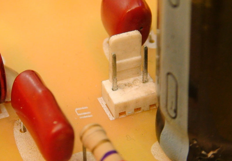
The signal input features a three-pin connector, from which the center pin should be removed. The remaining pins are used for: Signal input: receives the audio signal from a preamplifier or directly from a player. Ground connects to the ground of the player or preamplifier. When connecting the signal, double-check that the signal and ground wires are not reversed, as this will result in poor sound quality and annoying noise. If you’re using a player without its own volume control, you can add a 10K-50K potentiometer between the player and amplifier. To do this correctly:
1. Connect the signal from the player to pin 3 of the potentiometer (left to right).
2. Connect the center pin of the potentiometer to the amplifier.
3. Connect pin 1 of the potentiometer to the ground of both the player and amplifier.
Note that if you’re using a preamplifier, it likely has its own volume control, making this step unnecessary.
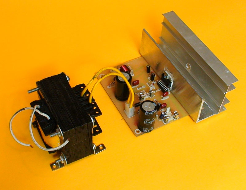
The 28 volt AC transformer
To construct the transformer for this amplifier, we utilized a 3.2 cm x 4 cm core. Since the grid voltage is 120Vor 220V, we wound: 377 turns of 23-gauge wire for the primary winding and 92 turns of 18-gauge wire for the secondary winding in countries using 120V. For countries with a 220V grid voltage, use: 721 turns of 26-gauge wire for the primary winding (AWG table) The secondary winding remains unchanged. If you can’t obtain the specified core size, you can use alternative materials as long as you can calculate the required turns using the formulas provided in our Transformer Calculation article. Simply ensure you can obtain the necessary core area in square centimeters.
This high-performance amplifier offers versatility in its applications. It can also be combined with a mono preamp to play music. Additionally, you can create a 180W stereo amplifier or add a low-pass filter to create a 2.1 amplifier system. We’ve tested this amplifier with a 300W, 8Ω, 12-inch Supertone speaker and recommend using speakers with a minimum rating of 200W, 8Ω, and 10 inches. However, with a suitable heatsink and fan, you can safely operate with two speakers in parallel, resulting in a 4Ω impedance. The possibilities in electronics are endless, and we hope that our contributions inspire you to bring your imaginative ideas and projects to life.
Download PDF File bellow
IT IS IMPORTANT that before you start building the amplifier circuit found in the PDF file, you read the written article thoroughly and watch the video. In many cases it is not enough to just view the PDF file.
>>>Download here<<< The PDF file with the schematic diagram, printed circuit board and bill of materials, for the creation of the super economical 90w amplifier .
>>>Download here<<< The PDF file with the schematic diagram, printed circuit board and bill of materials, for the creation of the super economical 180w amplifier ..