
100 Watts Mono Amplifier In Three Configurations
Hybrid amplifiers can be configured in three ways: complementary, quasi-complementary NPN, and quasi-complementary PNP. Power amplifiers come in various forms, primarily:
1. Discrete amplifiers: Built transistor by transistor, with each stage constructed independently. This approach allows for high power output and is preferred for high-fidelity applications.
2. Integrated amplifiers: Utilize pre-fabricated ICs (Integrated Circuits) for a more compact design.
3. Hybrid amplifiers: Combine discrete and integrated approaches, offering a balance between performance and compactness.
Discrete amplifiers, in particular, offer high power output and flexibility, making them a popular choice among audiophiles. Typically, six transistors are sufficient to achieve satisfactory power amplification in a discrete amplifier.
Modern Discrete Amplifier Designs
Today’s discrete amplifiers typically fall into two categories: complementary and quasi-complementary designs. Quasi-complementary amplifiers can feature either NPN or PNP output transistors, although other configurations may occasionally emerge.
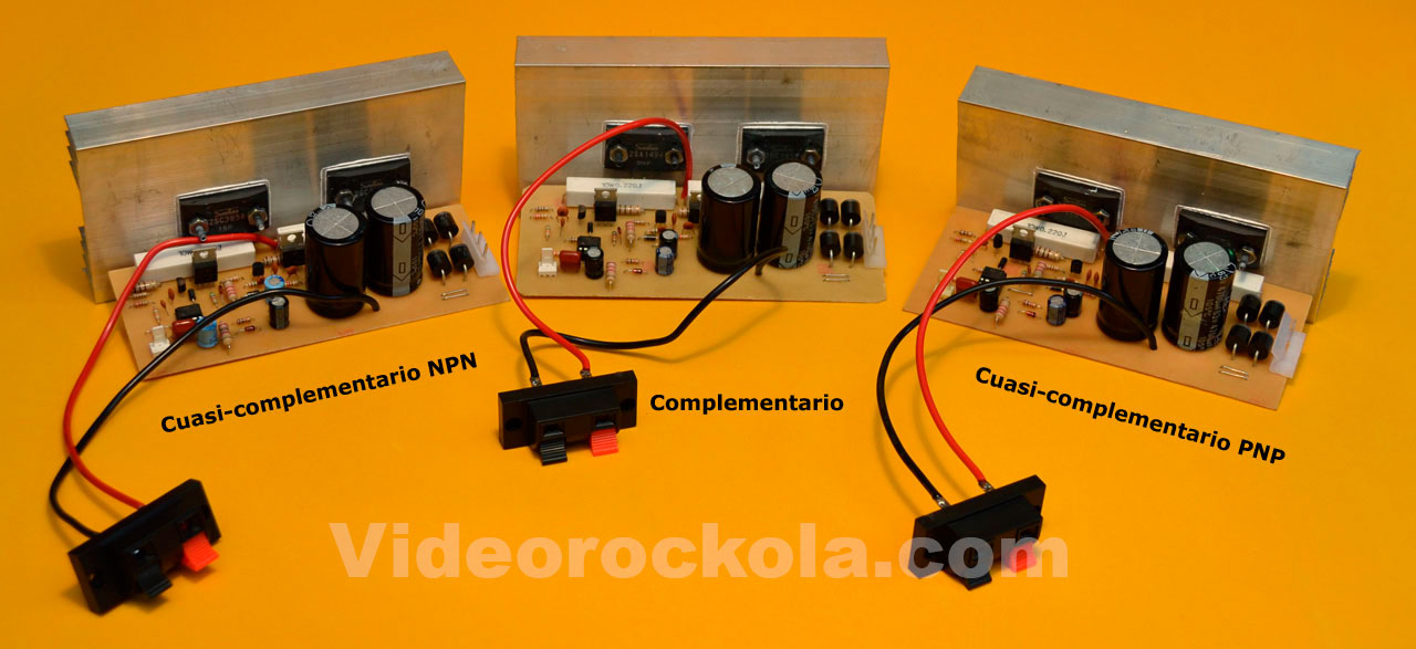
In this discussion, we’ll explore complementary and quasi-complementary amplifiers, using a hybrid amplifier as an example. This hybrid design employs an integrated circuit as an input stage, replacing the traditional differential pair. We’ve built this hybrid amplifier in three distinct versions.
Note that our upcoming discussion focuses on transistor types and polarities, which is distinct from amplifier classes, such as:
– Class A
– Class AB
– Class D
– Class H
These amplifier classes can also be implemented using complementary or quasi-complementary configurations.
Complementary Amplifiers
Complementary Amplifiers: Design and Limitations

A complementary amplifier features a power amplifier stage with both positive (NPN) and negative (PNP) base transistors. These transistors work together, with the NPN amplifying positive half-cycles and the PNP handling negative half-cycles. This configuration reproduces the complete audio sine wave. The concept of complementary amplifiers originated from H.C. Lin and was developed by General Electric Co. and other companies. Today, complementary amplifiers dominate the power amplifier market, offering impressive performance and acceptable fidelity. However, complementary amplifiers are not without limitations. Transistors have a manufacturer-specified gain (hFE or Beta), which varies between transistor types. For instance:
– Low-power transistors (e.g., A1015) have higher Beta values (~180)
– High-power transistors (e.g., 2SC3858) have lower Beta values (~30)
– Complementary transistors (e.g., 2SA1494) exhibit different Beta values (~100)
This discrepancy in transistor response leads to Crossover Distortion, a type of distortion occurring during wave crossing. Despite optimal BIAS design and calibration, this distortion persists.
It’s essential to note that complementary amplifiers are not inherently noisy. In fact, they often outperform integrated amplifiers in terms of cleanliness. However, they may exhibit slightly higher noise levels compared to quasi-complementary amplifiers—a difference only discernible to sound experts or through oscilloscope analysis. To the average listener, complementary amplifiers sound flawless.
NPN Quasi-Complementary Amplifiers
Quasi-Complementary Amplifiers: Design and Conversion

A quasi-complementary amplifier uses output transistors of the same polarity to produce both positive and negative half-cycles. In this example, we’ll explore a quasi-complementary amplifier using NPN transistors. To convert a complementary amplifier to a quasi-complementary NPN amplifier, you’ll need to make a few modifications, like relocating the 0.22-ohm resistor (R17) that polarizes the PNP transistor. Move it from between the PNP transistor emitter and the output to between the new NPN transistor emitter and –Vcc.