
Part 1
Construct a quasi-complementary transistor audio amplifier featuring a differential pair configuration.
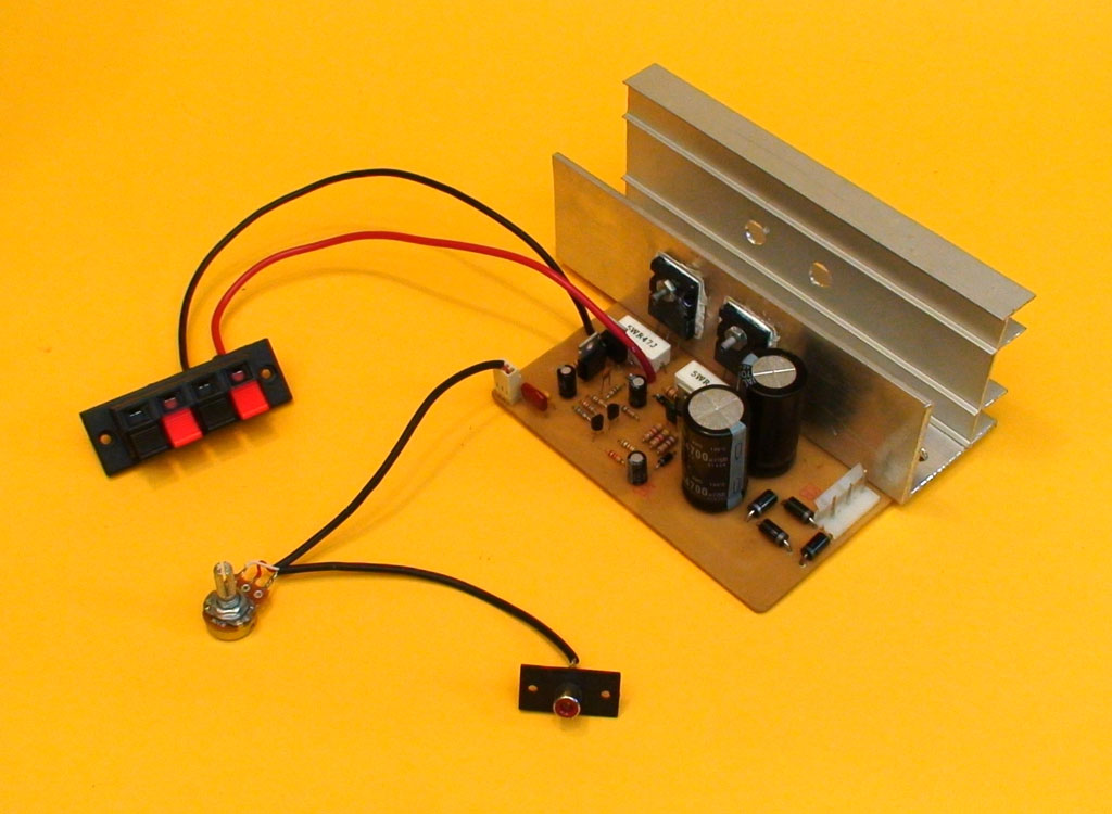
In this part we present a 100W monophonic amplifier, suitable for use as a standalone unit or in combination with a preamp. For stereo applications, you can assemble two identical stages, sharing the same transformer, to create a stereo amplifier. Alternatively, our projects section features a stereo version with tone control, named the 200W amplifier. This project is ideal for individuals seeking to learn about and understand transistor operation. The required materials are readily available and budget-friendly. The amplifier’s configuration is classified as a quasi-complementary class AB amplifier with differential torque.
Key components include:
– A pair of A733 or A1015 PNP transistors in differential pair configuration
– TIP41 (NPN) and TIP42 (PNP) driver transistors, which are complementary
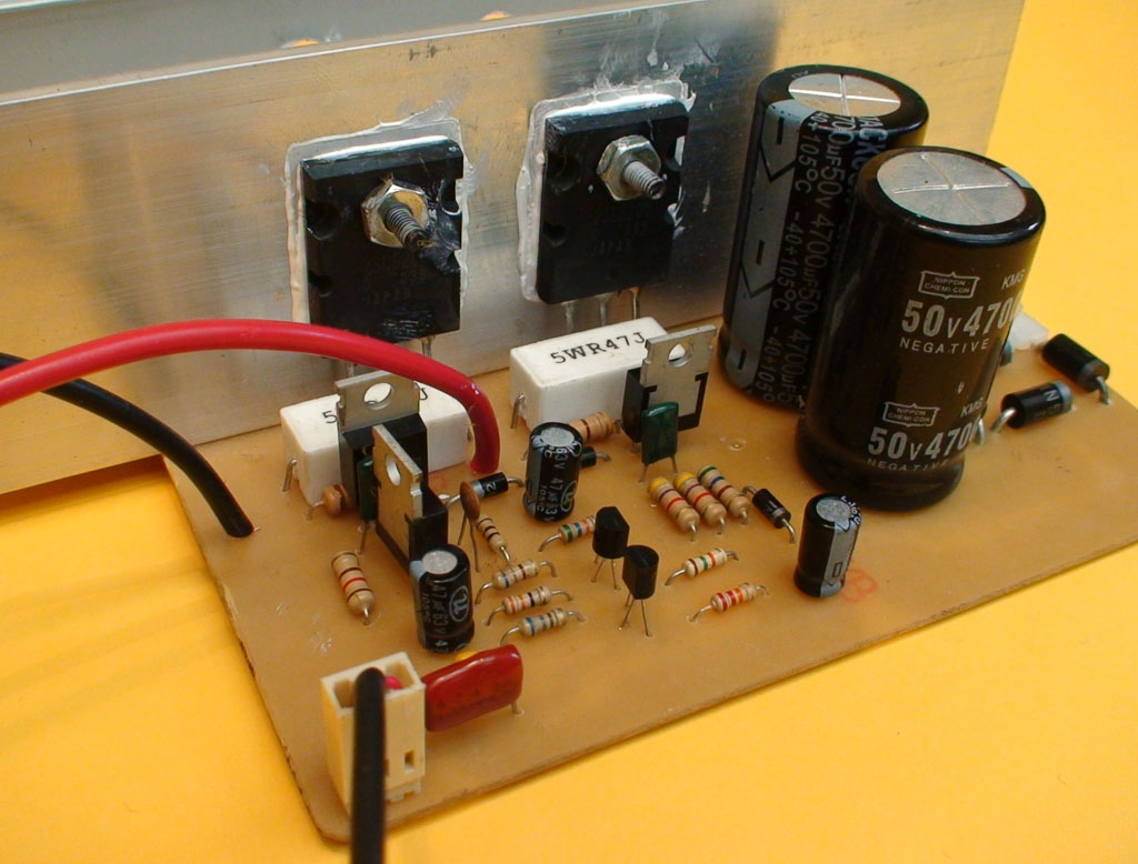
– 2SC5200 NPN output transistors, capable of handling high power levels
This tutorial offers a comprehensive, step-by-step guide to building the amplifier. To achieve success, prior knowledge of basic electronics and experience in assembling electronic projects is essential. Beginners are advised to consult our electronics tutorial section, which provides expert tips, tutorials, and practical guidance to help navigate potential challenges.
One of the amplifier’s key features is its adjustable gain, which can be fine-tuned by replacing a single resistor. For example, upgrading the 56K resistor between the A733 base and output to 100K increases gain, can result in some loss of fidelity. Conversely, substituting it with a 33K resistor enhances sound clarity, but reduces gain. This adaptability is particularly beneficial when using a preamp to optimize gain levels.
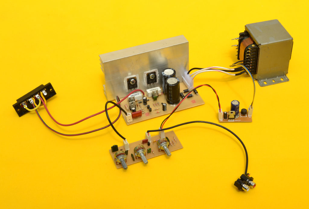
Rectifier Source
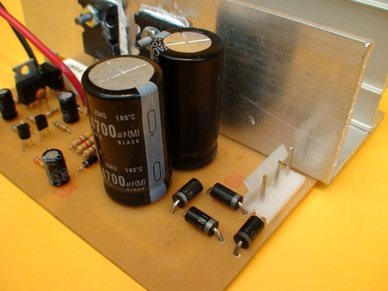
All sound amplifiers require DC power. This design utilizes a symmetrical power supply, comprising four diodes and two capacitors, to convert AC to DC. The power supply features a center tap, which serves as the ground reference point. The transformer drives the power supply, stepping down the mains voltage to the required 36 x 36 volts. The transformer’s output is then fed to a diode bridge, which converts the AC voltage to a pulsating DC voltage. The capacitor filters this voltage, maintaining a stable output. It’s essential to note that the rectified voltage is 1.4141 times the AC voltage. Therefore, for an amplifier operating at +/-46 volts DC, a transformer rated for 36 x 36 volts AC is required. In terms of capacitor selection, a minimum value of 4,700 microfarads is recommended. However, for optimal performance, we suggest using 6,800 microfarad capacitors rated at 63 volts.
Power Transistors
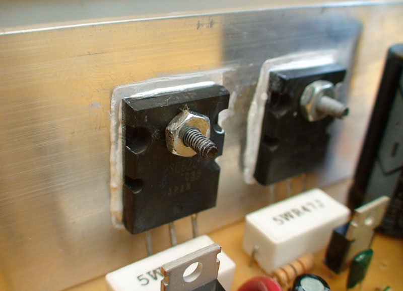
To ensure safe operation, power transistors must be electrically isolated from each other and the heatsink. This is accomplished using mica insulators and plastic bushings (referred to as “Pas murals” in Colombia). Additionally, apply silicone grease to enhance heat transfer between the transistors and the aluminum heatsink. The amplifier design utilizes 2SC5200 output transistors. For applications requiring a higher voltage (40 x 40V AC), consider replacing these transistors with higher-power alternatives, such as the 2SC3858.
Cooling is Essential
When building an amplifier, a frequent error is insufficient insulation between the transistors and the heatsink. To check for proper insulation, switch your multimeter to continuity mode. Connect one lead to the heatsink and the other to the output transistor’s collector (center pin). A correct reading will show infinity (∞), indicating no electrical connection. If the measurement reveals any impedance or continuity, it signals inadequate insulation, which can lead to a disastrous short circuit between the transistors or between the voltage and ground, especially if the heatsink is grounded.
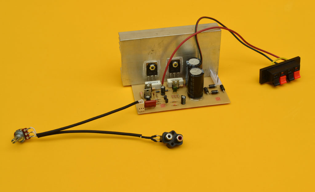
Audio Signal Input
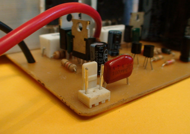
The signal input is facilitated by a 3-pin 2.54mm MOLEX connector, modified by removing the center pin. The remaining two pins serve distinct purposes: one pin is dedicated to receiving the audio signal from a preamplifier or playback device, while the other pin provides the ground connection. When connecting the signal, exercise utmost caution to avoid mistakenly swapping the signal and ground pins, which can result in poor sound quality and unwanted noise.
The Volume Potentiometer
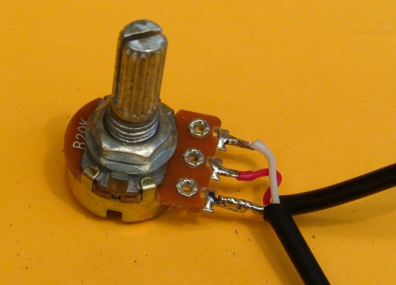
Installing a potentiometer with a value of 10K to 50K is crucial, and it must be positioned between the playback device and the amplifier. To connect the potentiometer correctly:
1. Connect the signal from the playback device to pin 3 of the potentiometer (left to right).
2. Link the central pin of the potentiometer to the amplifier.
3. Connect pin 1 to the ground of both the playback device and the amplifier.
Note that if you’re using a preamplifier, it typically has its own built-in potentiometer, making this step unnecessary.
The Transformer
Transformer Construction Guidelines: Core size: 3.2 cm x 5 cm for 120V public network voltag primary winding 315 turns of 22-gauge wire secondary winding 190 turns of 17-gauge wire to create a center tap wind 95 turns solder a cable to mark the center point add the remaining 95 turns alternative method wind 95 turns with doubled wire (see transformer construction video). For 220V public network voltage: primary winding: 577 turns of 25-gauge wire (AWG table) secondary winding remains the same as above
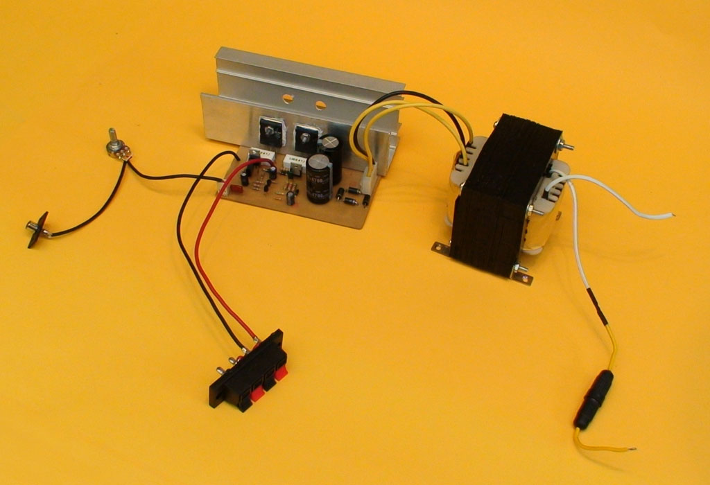
Measurements
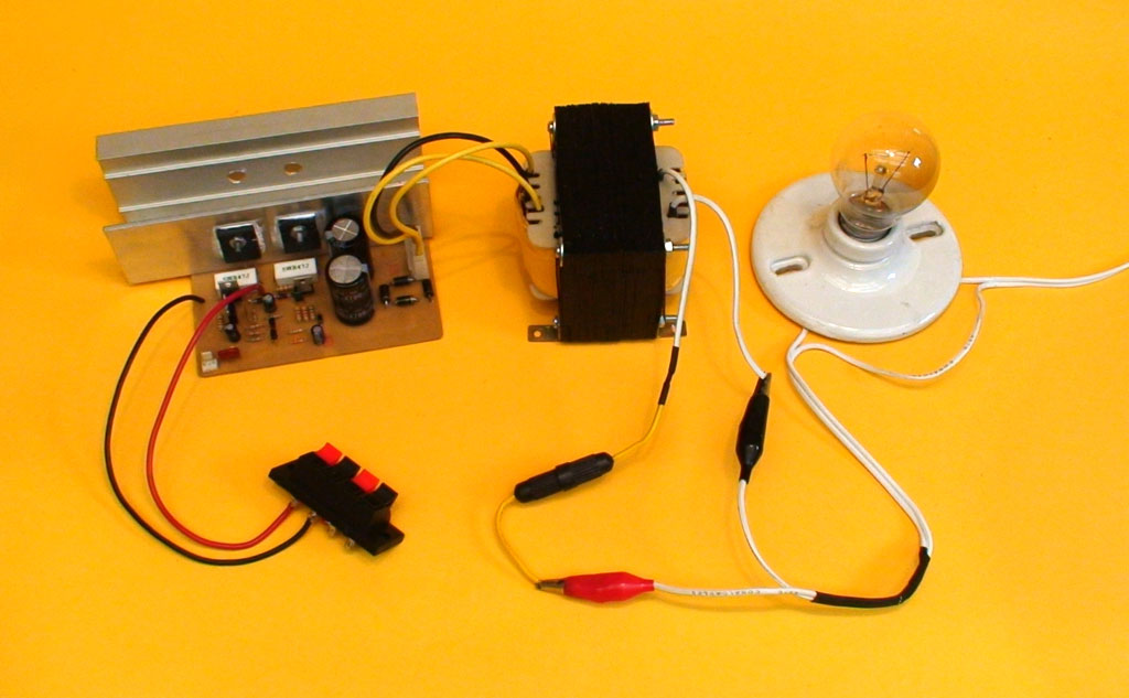
Pre-Power-On Checks: Before turning on the amplifier, perform the following measurements with a multimeter set the multimeter to continuity mode and measure the AC input without connecting the transformer. The reading should indicate no connection. Measure the speaker output; it should also show no connection. Connect the amplifier to the public network using a series circuit (as shown in the photo). Ensure the amplifier is not connected directly. Verify the series light bulb does not illuminate. Set the multimeter to DC voltage mode and measure the output voltage. The reading should be 0 volts lso perform the BIAS measurement; the voltage should read 0.7V. Finally, measure the voltage of the power source after the capacitors.
If the above measurements give you the correct results, then you can already connect the speaker to the output and an audio signal to the input. It’s time to try it out.If you are inexperienced, we recommend making a simpler, lower voltage before doing this amplifier. Lack of experience can lead to failure, especially in those cases where a component comes from the factory and we do not know how to track problems.
For this amplifier, we recommend using speakers between 100W and 200W of power, with an impedance of 8 ohms. Remember to use a 2 amp fuse at the transformer input.Next, on the next page, we will see the quasi-complementary version with PNP or negative base transistors. It’s just as good as the version we just saw.
At the end, you will find the download link of a paid PDF file that contains what you need to build both versions of the amplifier. Note this PDF file expires after a time frame of 1 week so please make copies of it before the time elapses to avoid buying the file again.
Part 2
We introduce a quasi-complementary amplifier design utilizing PNP transistors, providing a reliable alternative for situations where NPN transistors are scarce or unavailable.
Let’s explore the quasi-complementary amplifier design using PNP (negative base) transistors. This version functions similarly to the previous NPN transistor design, with some modifications to accommodate PNP transistors.The motivation behind developing this PNP version was a concern raised by one of our followers, who struggled to find NPN transistors. Interestingly, when I searched for PNP transistors, I found them to be more readily available and affordable than their NPN counterparts. For testing, I used the 2SA2151 transistors, which were half the price of the 2SC5200 and widely available. Other suitable PNP transistors for this amplifier include the 2SA1494, 2SA1943, and 2SA1301, or any high-power, genuine PNP transistor.
Schematic
The electrical diagram below closely resembles the NPN version, with subtle modifications to the output transistors and drivers. To gain a more comprehensive understanding of transistor amplifier configurations, we suggest checking out our article on the 100W Amplifier version 3.0, which explores the three primary configuration options in detail. Schematic image here
The diagram also indicates specific voltages that should be present at various points in the amplifier to ensure proper functioning. For instance:
– The junction of the A1015 emitters should measure 0.7V. A deviation from this value may indicate faulty or counterfeit transistors.
– The BIAS measurement on the diode connected to the TIP41 base should read 0.7V.
– The same 0.7V measurement should be observed at the junction of the 10 ohm resistor and the
TIP41 collector. Achieving perfectly symmetrical BIAS can be challenging, especially considering the inconsistent quality of modern transistors. However, if the measurements are close to the expected values, the amplifier should function properly. For example, if the A1015 differential measures 0.7V, the output measures 0V, and the BIAS measures 0.4V and -0.8V, the amplifier will likely work without issues. Don’t be alarmed if you can’t achieve perfect BIAS symmetry. However, if the voltage differences are extreme, it’s essential to verify the authenticity and quality of the transistors. Severe BIAS mismatch can lead to excessive heat generation in the output transistors and potentially poor sound quality
These amplifiers are engineered for a flat frequency response. Adding a volume potentiometer at the input provides simple volume control. However, to fully unleash the amplifier’s potential, we recommend pairing it with a preamplifier. During testing, we initially used the amplifier with just a potentiometer, then added a discrete preamp with bass and treble tone controls. The result was exceptional: a clean, pleasant sound. The amplifier components are ready for cabinet installation. When connecting the signal input, preamp, and amplifier, shielded cables are essential to prevent parasitic noise interference. For optimal performance, we recommend powering the preamplifier separately using a regulated power supply with a 12-18V voltage range.
Amplifier Fitted Into Your Cabinet
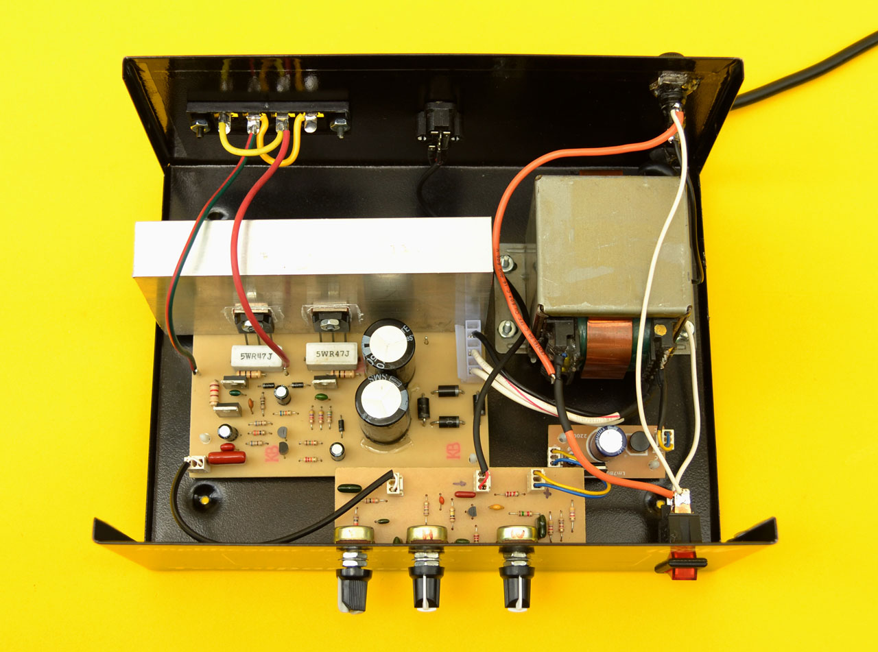
A well-presented amplifier is crucial for showcasing its value. Even with a high-quality circuit, a poorly presented amplifier can deter potential buyers or lead to low offers. To maximize its value, it’s essential to house the amplifier in an attractive and protective box or cabinet. Ensure a neat and organized layout inside the box, with the following features A fuse holder with a protection fuse for the power input
– A power switch in series with the fuse and transformer
– Cables cut to the necessary length, with some slack for easy maintenance and removal
A professional presentation not only enhances the amplifier’s appearance but also protects its internal components and demonstrates attention to detail
The adjustment of the cards must be done in such a way that they are isolated from the floor of the box, except for the tracks that are ground. The power cable must have a ground pole and this is screwed to the chassis of the transformer.
NOTE : The amplifier shown in the picture does not have a fan, as it was designed for low-voltage operation (30+30V AC) and intermittent use as a public address system in a company setting.However, if you plan to operate this amplifier at its maximum voltage (36+36 VAC) and with a 4-ohm load, installing a fan is ABSOLUTELY NECESSARY to prevent overheating.
Amplifier Ready for Home Use
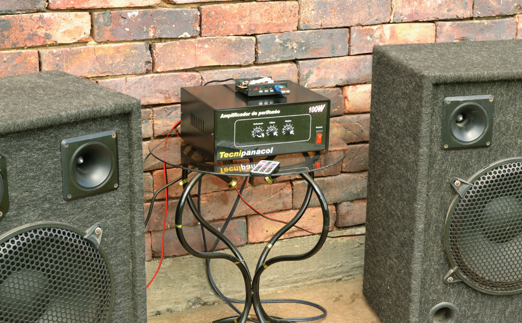
This amplifier is versatile and can enhance your home entertainment experience in various ways, such as:
– Adding ambient sound to your room
– Amplifying your computer’s audio
– Powering small parties with an MP3 player
We’ve successfully tested this amplifier with a range of speakers, including 12-inch 300W peak speakers, 100W mid-range speakers, and 100W tweeters, achieving clear and full-range sound. Note that the speaker power can be lower, as a 300W peak speaker typically delivers around 140W RMS. Therefore, speakers with a rating of 100W RMS (or approximately 230W peak) would be suitable.
Public Address Amplifier or Pager
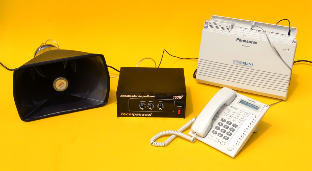
Our goal is to provide income-generating opportunities for our followers through projects like this. We’re excited to share a commercial application for our 100W amplifier: a public address amplifier or pager system for companies. In larger companies, it’s common to need to page employees over a public address system. Our amplifier can power multiple horns throughout the facility, ensuring everyone can hear announcements. Many companies already have a telephone exchange or hybrid communications system, which allows for intercommunication between departments and external calls. These systems often feature a preamplified audio output called PAGING. This output enables authorized users to send messages to the amplifier from any extension, allowing announcements to be broadcast over the speaker system. Notably, all Panasonic telephone systems have this paging function, although it’s often underutilized. We hope this information is helpful and highlights the cost-effectiveness of implementing this system.