
In this section we are to be learning on how 120V or 240V is transported and distributed to our cities and homes in great detail to broaden your understanding of electrical and electronics.
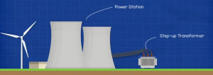 Electricity is generated at the power station, which is usually located far away. The power station generates AC or alternating current, and is connected to a step-up transformer. This transformer increases the voltage to reduce losses and is connected to the grid.
 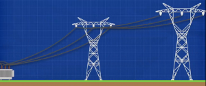 The grid carries high-voltage electricity over long distances to towns and cities.
 ![]() Once it reaches the towns and cities, it will enter a step-down transformer, which will decrease the voltage to a safer level. From here it will be distributed locally into smaller circuits on different streets or groups of properties. These distribution cables will be connected to a smaller transformer, usually pole-mounted, which again reduces the voltage down even further to a level safe enough for residential use. On the property will be an electricity prepaid meter, which will read how much electricity has been used, and the electricity company will use this to invoice the property. The transformer will be connected to the prepaid meter by some cables, which can run above the ground or underground. These cables will be two hot wires and a neutral wire.
Once it reaches the towns and cities, it will enter a step-down transformer, which will decrease the voltage to a safer level. From here it will be distributed locally into smaller circuits on different streets or groups of properties. These distribution cables will be connected to a smaller transformer, usually pole-mounted, which again reduces the voltage down even further to a level safe enough for residential use. On the property will be an electricity prepaid meter, which will read how much electricity has been used, and the electricity company will use this to invoice the property. The transformer will be connected to the prepaid meter by some cables, which can run above the ground or underground. These cables will be two hot wires and a neutral wire.
Inside the transformer we have two coils of wire. The primary coil is connected to the power station, and the second coil will be connected to the property. The two hot wires are connected to each end of the secondary coil, and the neutral is connected to the center of the coil.
So, if we get inside the property, we find a main service panel, which is sometimes called a distribution box or breaker box. If we remove the cover and look inside, we first find the main breaker. This is usually first or located at the top of the panel, but it might be at the bottom as well. The two hot wires from the electricity prepaid meter will connect directly to the input of the main breaker. Coming out of the main breaker would be two main busbars. These are basically exposed metal sheets that carry electricity to the rest of the circuit breakers.
However, we’ve shown the current flowing in green dashes. This is AC, or alternating current. These busbars, as well as the lugs, are live, or hot. The main breaker can be manually flipped to cut the power to everything down it. The main breaker will also provide overcurrent protection to the property because it is rated to handle a certain amount of electric current passing through it, this is between 100 and 200 amps. If this value is exceeded then it will trip automatically to try and protect the property and its electrical circuits.
Now, inside the distribution box, we have a neutral and ground connector block bar. This is basically a strip of metal with lots of holes and screws in it; this is where neutral and ground wires will sit, and the screws will lock them in place. In this example we have a block on either side of the panel. As this is a main panel, the two busbars can be joined together so we have a connector bar between them. This way we have a shared neutral-ground busbar.
So, from the electricity pre-paid meter, you have the neutral wire connected to the neutral bar and metal casing of the service panel to return the used electricity back to the transformer. So, the two hot wires will provide electricity, and once it is used, it will return to the transformer via the neutral bar. This is still AC, or alternating current. If we were to take a multimeter and connect one lead to the busbar and the other lead to the neutral bar, we would get a reading of around 120 volts. If you don’t already have a multimeter, then click here to get one at a cheaper price. It’s essential for your toolkit, electrical testing, and fault finding. If we connect the other lead to neutral and the other busbar, we get a reading of 120 volts. If the multimeter leads are placed on the two main busbars, then we get a reading of double the voltage, around 240 volts.
So why is that? What’s happening here? So, when we look at how the transformer is connected to the main service panel, we have the two hot busbars connected to the ends of the secondary coil of the transformer, and then we take the neutral busbar connected to the center of the secondary coil. So basically, when we connect across the busbar and the neutral bar, we’re only using half of the coil, so we are only picking up half of the electrical voltage the transformer can provide; that way, we get 120V. When we connect to the two busbars, we’re connecting to the full length of the coil, so we’re picking up the full voltage that the transformer can provide; that’s why we get 240 volts. If you want to learn how transformers work, then check out Transformer Basics.
Now coming back to the panel, we have our circuit breaker connected to the bus bar. These will look something like this with a black plastic casing and a toggle switch on top. This controls the flow of electricity into individual circuits in the property. It can be mainly tripped to cut power, but it also has two important features, like
Overload protections the circuit breaker is rated to handle a certain amount of electrical current, and when appliances or lights are connected to the circuit, they will each increase the current in the circuit. If too many things are plugged in and turned on, then eventually the current will be more than the breaker can handle, and it will automatically trip to cut the power off to the circuit and protect the property.
The second feature is short circuit protection. When the hot and neutral wires come into direct contact with each other, the current will dramatically increase almost instantly, and when this occurs, it creates a magnetic field that will trip the breaker and cut the power automatically. Now, let’s have a look at how the circuit breaker is connected to the electrical circuit with a simple light fitting that is controlled by a switch. We take the hot wire from the breaker and run this to the switch. We then run another wire from the switch to the light. From the light fitting, we have a neutral wire that carries the return current back to the neutral busbar. We then take the ground wire from the metal casing of the light fitting and of the switch back to the neutral busbar. The purpose of the hot wire is to carry the electric current to the light fitting. The purpose of the neutral wire is to carry the used electric current back to the main panel and then back to the transformer. The purpose of the ground wire is to provide protection for fault currents.